
Stability and deformation control structure of mountainside high-filled embankment and construction method

A deformation control and embankment technology, applied in infrastructure engineering, roads, roads, etc., can solve problems such as insufficient subgrade drainage measures for anti-overturning measures, uneven settlement at the junction of filling and excavation, seepage damage of slopes, etc., and achieve water isolation Good effect, improved anti-overturning ability, strong drainage ability

Active Publication Date: 2017-12-22
ZHEJIANG UNIV CITY COLLEGE
View PDF6 Cites 5 Cited by
  • Summary
  • Abstract
  • Description
  • Claims
  • Application Information

AI Technical Summary

Problems solved by technology

[0004] To sum up, the traditional half-fill and half-excavation embankment construction with high fill near the mountain often results in uneven settlement and embankment slippage at the fill-excavation interface due to inadequate treatment measures for the fill-excavation interface, anti-overturning measures for the retaining wall, and subgrade drainage measures. Destruction, high retaining wall instability, slope seepage damage embankment and other problems, it is urgent to solve these problems through improved technology

Method used


Image

  • Stability and deformation control structure of mountainside high-filled embankment and construction method
  • Stability and deformation control structure of mountainside high-filled embankment and construction method
  • Stability and deformation control structure of mountainside high-filled embankment and construction method

Examples


Embodiment Construction

[0038] The present invention will be further described below in conjunction with the accompanying drawings and embodiments. While the invention will be described in conjunction with the preferred embodiments, it will be understood that it is not intended to limit the invention to the described embodiments. On the contrary, the invention is to cover alternatives, modifications and equivalents, which may be included within the scope of the invention as defined by the appended claims.

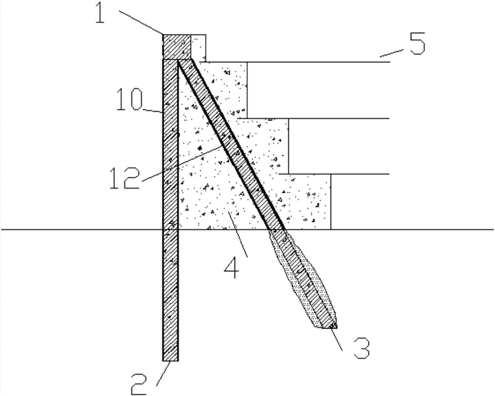
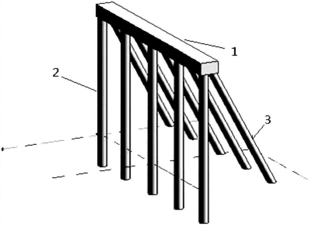
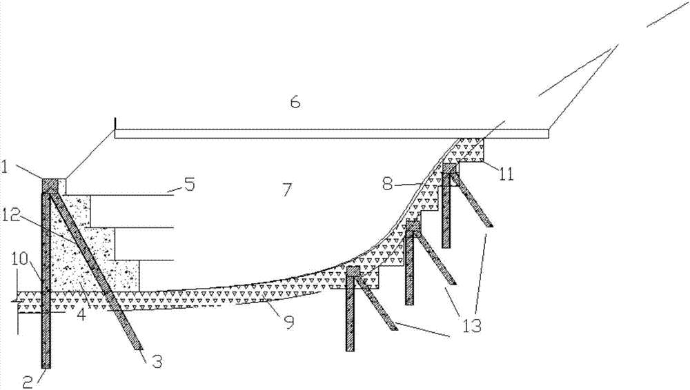
[0039] Such as figure 1 The human-shaped mini-pile 13 shown is formed by cross-lapping the vertical pile 2 and the inclined pile 3 through the crown beam 1, and the top of the crown beam 1 is flush with the top of the stepped foam lightweight concrete retaining wall 4. The vertical pile 2 is mainly used for bending resistance, and the steel pipe concrete pile with a diameter of 300mm-500mm is used; the oblique pile 3 is mainly used for pulling resistance, and the gravel grouting pile with a diame...


PUM

PropertyMeasurementUnit
Diameteraaaaaaaaaa
Thicknessaaaaaaaaaa

Abstract

The invention relates to a stability and deformation control structure of a mountainside high-filled embankment. The structure comprises a step type foam lightweight concrete guard wall arranged on the outer side of the embankment and excavation steps arranged in the interface of the embankment and a slope, wherein multiple groups of herringbone micropiles are arranged at the step type foam lightweight concrete guard wall and the excavation steps, and each herringbone micropile is formed by a vertical pile and an oblique pile through cross overlap joint of top beams at the tops; the vertical piles are steel tube concrete piles, and the oblique piles adopt crushed stone grouting piles; the inner facade of the step type foam lightweight concrete guard wall is poured into a step shape, each step is connected with a reinforcing mesh, one end of the reinforcing mesh is embedded into the step type foam lightweight concrete guard wall, and the other end of the reinforcing mesh is embedded into the embankment. The structure has the benefits as follows: the anti-sliding capability is high, and deformation of the interface of the newly-filled embankment and the slope is small; the drainage capability of the embankment is high, and the water insulation effect is good; the embankment retaining structure is high in stability; foam concrete is light in weight, and sedimentation is small.

Description

technical field [0001] The invention belongs to the field of embankment engineering, and in particular relates to a device and a construction method for preventing embankment slippage by human-shaped miniature piles, which are suitable for the construction of high-fill embankments near mountains, especially half-fill and half-fill high steep slopes with high requirements for embankment stability and safety. Digging embankment construction. Background technique [0002] The embankment near the mountain is a special subgrade. In order to save engineering investment and reduce the damage of natural hillside excavation during the route selection, it is generally distributed in the half-filled and half-dug road section and the section near the tunnel entrance. Because the foundation soil layer is in the soft-hard transition In this area, the embankment stability and settlement deformation control are quite technically difficult. A large number of surveys have found that the cons...

Claims


Application Information

Patent Timeline
IPC IPC(8): E01C3/00E02D3/00E02D3/10
CPCE01C3/00E02D3/00E02D3/10
Inventor 崔允亮周联英王新泉齐永洁王新
Owner ZHEJIANG UNIV CITY COLLEGE
Learn More