Spherical robot driven by orthogonal-position double omnidirectional wheels
A spherical robot and omni-directional wheel technology, applied in motor vehicles, transportation and packaging, etc., can solve the problems of asynchronous movement, speed and phase difference, and difficult robot trajectory, so as to achieve lower center of gravity, simple structure, and lower engineering cost effect
- Summary
- Abstract
- Description
- Claims
- Application Information
AI Technical Summary
Problems solved by technology
Method used
Image
Examples
Embodiment 1
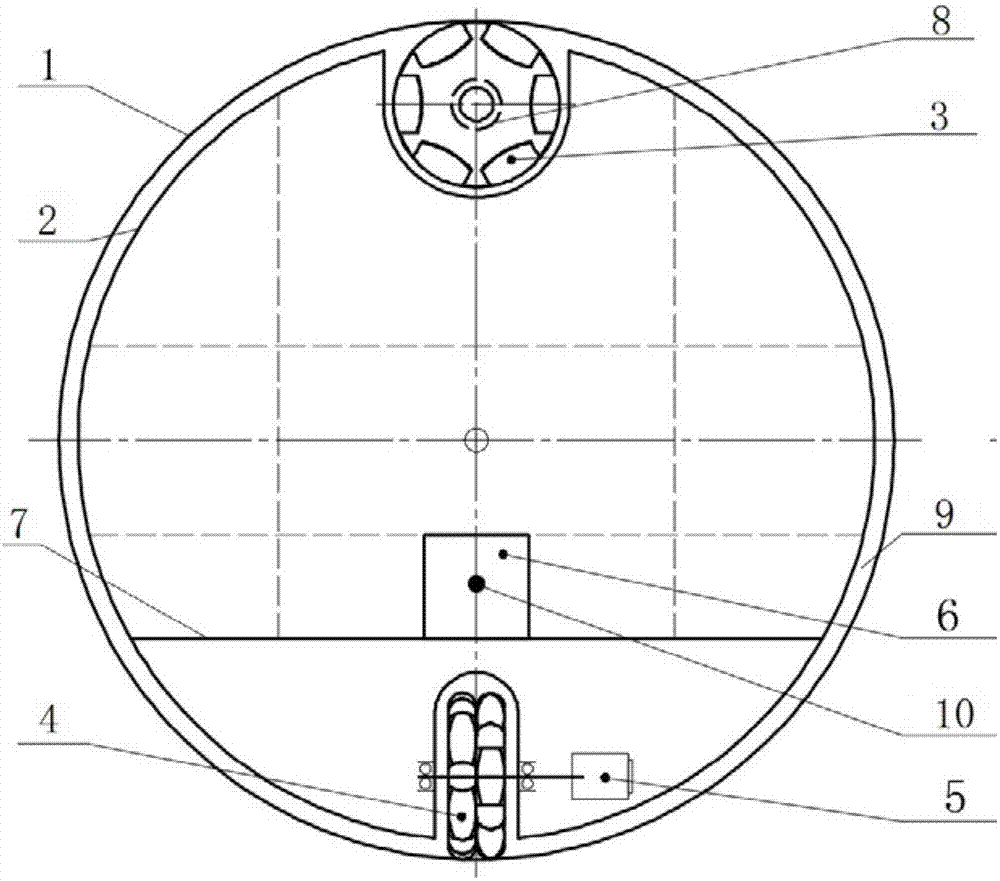
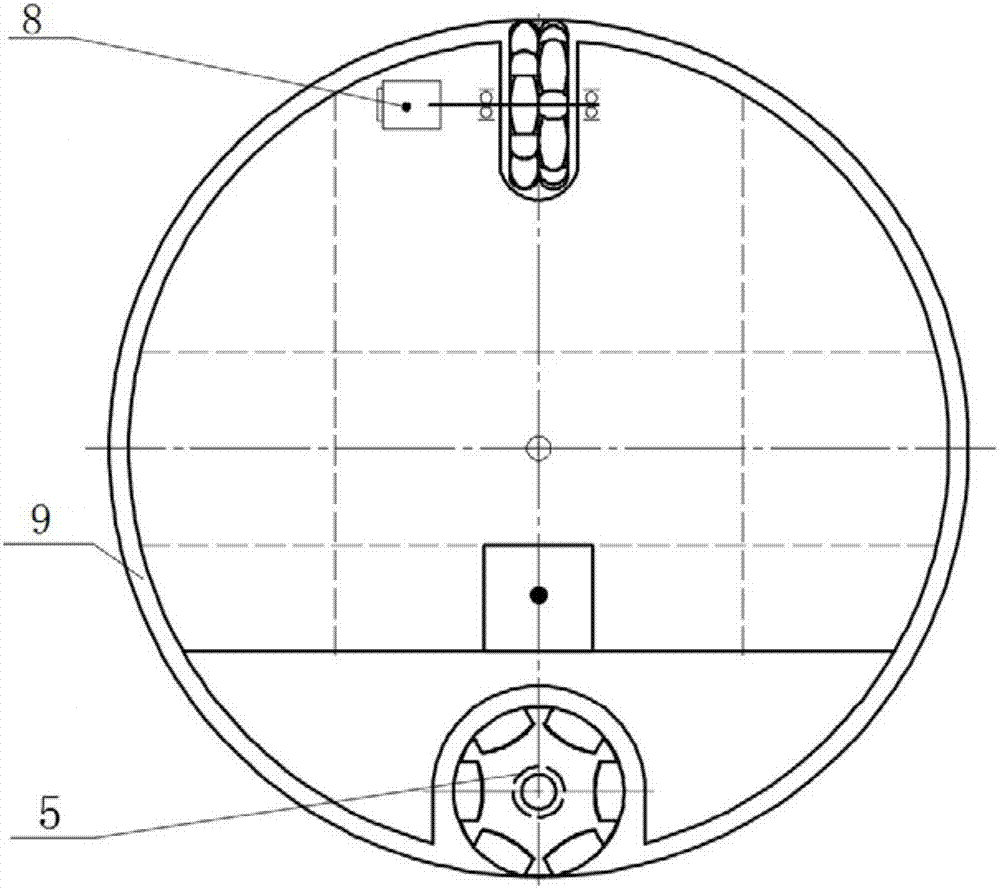
[0051] Such as figure 1 and 2As shown in the figure, an omni-directional spherical robot driven by orthogonal double omnidirectional wheels includes a spherical shell 1, a bracket 2, an upper omnidirectional wheel 3, a lower omnidirectional wheel 4, a walking drive 5, a control system 6 and a steering drive 8 .
[0052] The upper omni-directional wheel 3 is installed above the support 2, and the lower omni-directional wheel 4 is installed below the support 2. Further, the upper omni-directional wheel 3 and the lower omni-directional wheel 4 are arranged orthogonally at the two ends of the largest vertical diameter in the spherical shell 1 .
[0053] The bracket 2 has a certain degree of elasticity, which strengthens the pressure of the omnidirectional wheels 3 and 4 on the inner surface of the spherical shell 1, thereby obtaining sufficient frictional force to drive the spherical robot. The elasticity of the bracket 2 also contributes to shock absorption and buffering.
[...
Embodiment 2
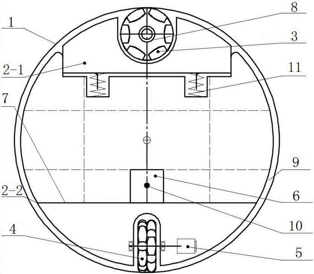
[0058] Such as Figure 3-6 As shown, an omni-directional motion spherical robot driven by orthogonal double omnidirectional wheels includes a spherical shell 1, an upper bracket 2-1, a lower bracket 2-2, an upper omnidirectional wheel 3, a lower omnidirectional wheel 4, and a walking drive 5. Control system 6, spring 11, steering drive 8.
[0059] The two omnidirectional wheels 3 and 4 are arranged orthogonally at the two ends of the maximum vertical diameter in the spherical shell 1; the lower omnidirectional wheel 4 is installed on the lower bracket 2-2, and the upper omnidirectional wheel 3 is installed on the upper bracket 2-2. 1, the upper bracket 2-1 and the lower bracket 2-2 are supported by a spring 11, and the spring 11 strengthens the pressure of the omnidirectional wheel on the inner surface of the spherical shell 1, thereby obtaining sufficient frictional force to drive the movement of the spherical robot. The spring 11 also contributes to shock absorption and cus...
Embodiment 3
[0064] Such as Figure 7 and 8 As shown, the difference between this embodiment and Embodiment 2 is that: the lower omni-directional wheels 4 are used to realize the turning motion of the spherical robot, and at the same time, the lower omni-directional wheels 4 are used to realize the walking motion of the spherical robot.
PUM
 Abstract
Description
Claims
Application Information
 - R&D Engineer
- R&D Manager
- IP Professional
- Industry Leading Data Capabilities
- Powerful AI technology
- Patent DNA Extraction
Browse by: Latest US Patents, China's latest patents, Technical Efficacy Thesaurus, Application Domain, Technology Topic, Popular Technical Reports.
© 2024 PatSnap. All rights reserved.Legal|Privacy policy|Modern Slavery Act Transparency Statement|Sitemap|About US| Contact US: help@patsnap.com


