
Serial driving plane motor structure and thrust calculation method thereof

A planar motor and series drive technology, applied in the direction of magnetic attraction or thrust holding device, electrical components, etc., can solve the problems of multi-driver, increase the number of coils, increase cost, etc., achieve simple solution method, increase calculation amount, cost reduction effect

Active Publication Date: 2017-12-15
TSINGHUA UNIV
View PDF7 Cites 3 Cited by
  • Summary
  • Abstract
  • Description
  • Claims
  • Application Information

AI Technical Summary

Problems solved by technology

[0004] When expanding the structure of the existing planar motor, it is found that for the moving coil planar motor, maintaining the original coil shape and increasing the load capacity means increasing the number of coils, which in turn requires more drivers, resulting in an increase in cost; for the moving iron planar motor The motor maintains the original coil shape to increase the motion stroke, which also means increasing the number of coils, and also faces the dilemma of increasing the driver and increasing the cost
[0005] In summary, the existing planar motors generally face the problem of increasing the number of drivers due to structural expansion, thereby increasing the cost

Method used


Image

  • Serial driving plane motor structure and thrust calculation method thereof
  • Serial driving plane motor structure and thrust calculation method thereof
  • Serial driving plane motor structure and thrust calculation method thereof

Examples


Embodiment Construction

[0060] The principle, structure and specific implementation of the present invention will be further described below in conjunction with the accompanying drawings and embodiments;

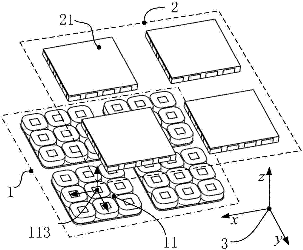
[0061] figure 1 It is a schematic diagram of an embodiment of the planar motor of the present invention, showing the main components of the planar motor, the coil array 1 and the magnetic steel array 2; wherein the coil array 1 is composed of several coil array units 11, and the magnetic steel array 2 It consists of several magnetic steel array units 21, the combination of which is as follows figure 2 As shown; the motor mover is provided with a motor mover coordinate system 3, and the origin of the coordinate system can be but not limited to be located at the geometric center of the motor mover; as Figure 4 The shown coil array unit 11 and the magnetic steel array unit 21 are both equal in size along the x direction, and both are also equal in size along the y direction; as image 3 As shown, ...


PUM


Abstract

Provided is a serial driving plane motor structure and a thrust calculation method thereof, relating to the structure design of a magnetic suspension plane motor. The plane motor includes a coil array and a magnetic steel array, the coil array consists of a plurality of completely identical coil array units, the magnetic steel array consists of a plurality of completely identical magnetic steel array units, the coil array units and the magnetic steel array units are equal in size in the x direction and in the y direction, the coil in each coil array unit is driven by different single-phase drivers, and the coils at the same relative positions in the different coil array units are serially connected on the same one driver. The structure is not only suitable for a moving coil planar motor structure, but also for the moving iron planar motor structure. When the structure is periodically expanded, only the added coils are connected in series to the corresponding drivers, the number of the drivers is not increased, the trust is large, and the expandability is good. The thrust calculation method can carry out the six-degree-of-freedom on the plane motor, and the thrust calculation quantity is small.

Description

technical field [0001] The invention relates to the design field of an xy two-dimensional motion platform, in particular to a planar motor structure and a thrust calculation method thereof. Background technique [0002] The magnetic levitation xy two-dimensional motion platform is the core component of the lithography machine equipment, which can realize the suspension of 6 degrees of freedom. Among them, the xy direction has a large range of motion. It is often used in the lithography machine workpiece table to carry silicon wafers to achieve large-scale movement in the plane. [0003] The existing planar motor structure has two kinds of moving coil and moving iron. The moving coil planar motor (such as patent CN105871257) has a fixed magnetic steel, and the coil moves. Most of the coils adopt the current distribution method of dq decomposition. Coil; moving iron type planar motor (such as patent CN101707472) coil is fixed, and the magnet steel moves, adopts the generalized...

Claims


Application Information

Patent Timeline
IPC IPC(8): H02N15/00
CPCH02N15/00
Inventor 张鸣朱煜袁丁杨开明成荣李鑫刘峰胡金春
Owner TSINGHUA UNIV
Learn More