
Pixel structure and its application to display panel

A pixel structure and pixel technology, applied in static indicators, instruments, etc., can solve the problems of brightness difference between adjacent pixels, horizontal or vertical bright and dark lines, affecting display quality, etc., and achieve the effect of quantization and smooth display panel.

Inactive Publication Date: 2017-12-15
HKC CORP LTD +1
View PDF7 Cites 6 Cited by
  • Summary
  • Abstract
  • Description
  • Claims
  • Application Information

AI Technical Summary

Problems solved by technology

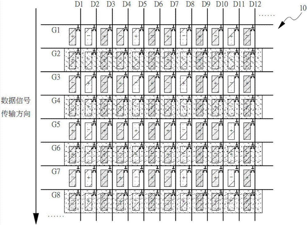
[0005] However, since the polarities of two adjacent pixels in the same column are the same, there is a large difference in the delay of the data signal reaching the adjacent pixels, which leads to differences in the brightness of adjacent pixels, causing horizontal or vertical bright and dark lines on the display This problem affects the display quality, especially in low gray levels. However, how to quantify the degree of horizontal or vertical bright and dark lines of a product, there is still no uniform standard

Method used

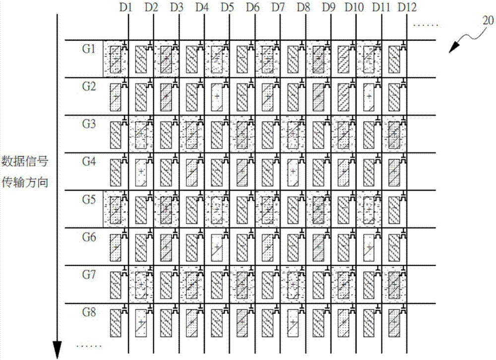
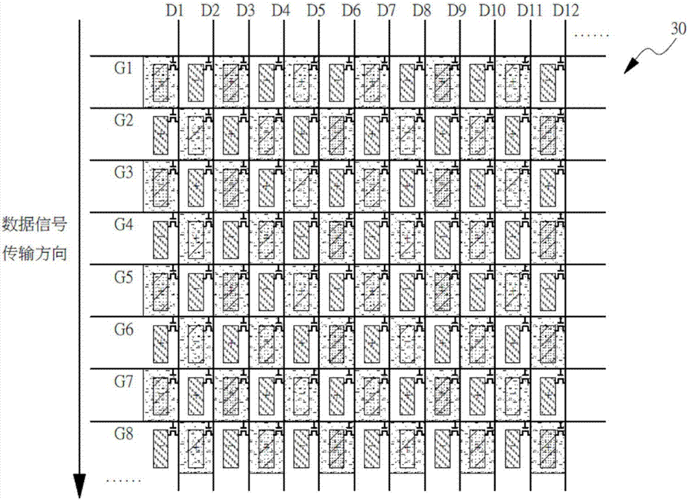

Image

  • Pixel structure and its application to display panel
  • Pixel structure and its application to display panel
  • Pixel structure and its application to display panel

Examples


Embodiment Construction

[0025] The following descriptions of the various embodiments refer to the accompanying drawings to illustrate specific embodiments in which the present invention can be practiced. The directional terms mentioned in the present invention, such as "up", "down", "front", "back", "left", "right", "inside", "outside", "side", etc., are for reference only The orientation of the attached schema. Therefore, the directional terms used are used to illustrate and understand the present invention, but not to limit the present invention.

[0026] The drawings and descriptions are to be regarded as illustrative in nature and not restrictive. In the figures, structurally similar units are denoted by the same reference numerals. In addition, the size and thickness of each component shown in the drawings are arbitrarily shown for understanding and ease of description, but the present invention is not limited thereto.

[0027] In the drawings, the thickness of layers, films, panels, regions,...


PUM


Abstract

The invention relates to a pixel structure and its application to a display panel. The pixel structure includes a plurality of array configured pixel units that are coupled to the corresponding scan lines and a data line and include a first pixel unit having a first pixel circuit; a second pixel unit having a second pixel circuit; and a shared switch having a first end coupled to a common electrode. The first pixel unit and the second pixel unit are coupled to different scan lines arranged at intervals, the control end of the shared switch and the first pixel unit are coupled to the same scan line, and the first pixel unit and the second pixel unit can charge or discharge at the same time or only one of the first pixel unit and the second pixel unit charges and discharges.

Description

technical field [0001] The present invention relates to a pixel design, in particular to a pixel structure and its application to a display panel. Background technique [0002] Liquid crystal display devices use the electrical and optical properties of liquid crystals to display images. Liquid crystals have anisotropy, for example, differences in refractive index and dielectric constant between the major and minor axes of the molecule. The molecular arrangement and optical properties of liquid crystals can be easily adjusted. A liquid crystal display device displays images by changing the alignment direction of liquid crystal molecules according to the magnitude of an electric field to adjust the transmittance of light passing through a polarizer. [0003] The liquid crystal display device includes a liquid crystal panel and a driving circuit, in which a plurality of pixels are arranged in a matrix form, and the driving circuit includes a gate driver for driving the scanni...

Claims


Application Information

Patent Timeline
Patent Type & Authority Applications(China)
IPC IPC(8): G09G3/36
CPCG09G3/36G09G3/3607G09G2300/0443G09G2300/0426G09G3/3677G09G3/3688G09G3/3614G09G2300/0439
Inventor 李泽尧
Owner HKC CORP LTD
Learn More