
Automatic sampling device

A sampling device and automatic sampling technology, applied in sampling devices and other directions, can solve problems such as hidden dangers of large climbing operations, high operation risks, and low sampling efficiency, and achieve the effects of reducing operation risks, improving sampling efficiency, and saving labor costs.

Pending Publication Date: 2017-12-15
SHENZHEN POWER SUPPLY BUREAU
View PDF4 Cites 5 Cited by
  • Summary
  • Abstract
  • Description
  • Claims
  • Application Information

AI Technical Summary

Problems solved by technology

However, there are obvious deficiencies in the existing sampling methods: First, there is a large hidden danger of climbing operations: according to the electrical safety work regulations, when the distance between the operating height and the ground exceeds 1.5m, a safety belt should be used, and the safety belt should be taken high hang low way
The installation position of the substation test insulator is generally 6-7m above the ground, and the sampling work requires climbing operations, but usually there is no higher part of the upper part of the test insulator to hang the safety belt, so in order to minimize the operation risk, usually Failure to sweep the upper insulator will result in insufficient and comprehensive sampling, which will eventually greatly affect the accuracy of the detection work
Second, the sampling efficiency is low: because the detection of the chemical composition of the dirt often requires the detection of the solid component first, and then the detection of the ionic component of the aqueous solution, the dirt sample taken initially must be in the form of a solid
However, the current sampling tool is usually an ordinary dust brush, which does not fit tightly with the insulator disc, and does not have good sample retention performance, resulting in low sampling efficiency
[0004] To sum up, the traditional dirt sampling technology on the surface of insulators has the defects of high operational risk and low sampling efficiency, and fails to play an effective supporting role in the subsequent chemical composition detection and further analysis.

Method used


Image

  • Automatic sampling device
  • Automatic sampling device
  • Automatic sampling device

Examples


Embodiment Construction

[0023] The following will clearly and completely describe the technical solutions in the embodiments of the present invention with reference to the accompanying drawings in the embodiments of the present invention. Obviously, the described embodiments are only some, not all, embodiments of the present invention. Based on the embodiments of the present invention, all other embodiments obtained by persons of ordinary skill in the art without creative efforts fall within the protection scope of the present invention.

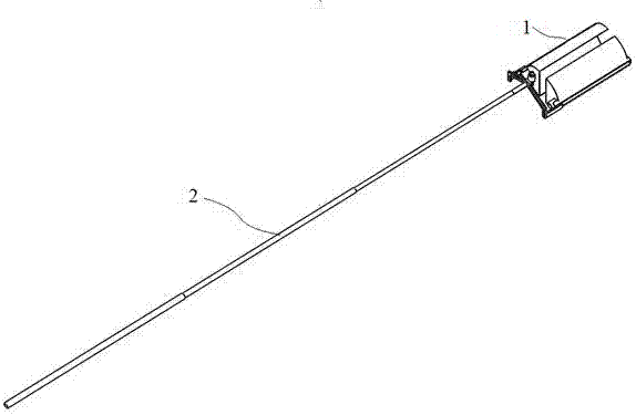
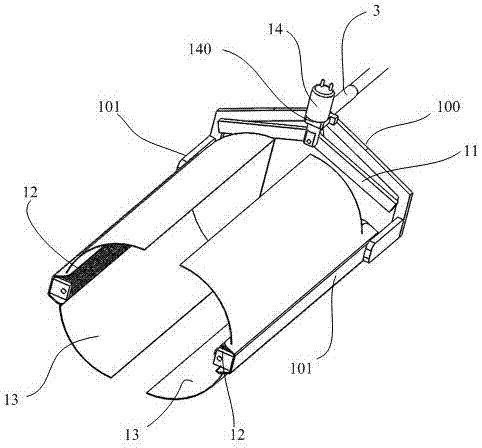
[0024] Such as figure 1 As shown, a schematic structural view of an embodiment of an automatic sampling device applied to the detection of dirt on the surface of substation insulators provided by the present invention is shown; and combined Figure 2 to Figure 3 shown. In this embodiment, the automatic sampling device includes: an automatic sampling mechanism 1 and an adjustable telescopic rod 2 connected with the automatic sampling mechanism 1;

[0025] Wherein,...


PUM

PropertyMeasurementUnit
lengthaaaaaaaaaa

Abstract

The invention discloses an automatic sampling device for sampling dirt on the surfaces of insulators of a transformer substation. The automatic sampling device comprises an automatic sampling mechanism (1) and an adjustable telescopic rod (2) connected with the automatic sampling mechanism (1), wherein the adjustable telescopic rod (2) comprises a mechanism body (10), two sample-preserving protecting covers (13), two sampling brushes (12), an electromagnetic assisting device (14) and two sampling brush spinning motors (15), the electromagnetic assisting device (14) is used for controlling an angle swinging connecting rod (11), and two ends of the angle swinging connecting rod (11) are respectively connected to the two sampling brushes (12). According to the embodiment of the invention, the automatic sampling device has the advantages of convenience in carrying and operation, high safety, good sampling effect and the like.

Description

technical field [0001] The invention relates to the technical field of dirt detection on the surface of substation insulators, in particular to an automatic sampling device for sampling dirt on the surface of substation insulators. Background technique [0002] With the development of industry, the phenomenon of artificial particle pollution has gradually become apparent; affected by it, the pollution flashover accidents that may be caused by the pollution of insulators pose a serious threat to the safe and stable operation of the power grid, so it is particularly important to effectively carry out anti-pollution work. In order to analyze the chemical composition of the dirt accumulated on the surface of the insulator, the high-voltage test personnel must sample the dirt from the surface of the experimental insulator in the substation. [0003] At present, the existing sampling method generally relies on manpower to ascend to work, and uses a dust brush to sample the dirt of...

Claims


Application Information

Patent Timeline
Patent Type & Authority Applications(China)
IPC IPC(8): G01N1/10
CPCG01N1/10
Inventor 云辰太任重黄文武张嘉乐曾雄杰林景福王朔
Owner SHENZHEN POWER SUPPLY BUREAU
Learn More