
Round joint used for cylinder and box beam

A technology of box girders and columns, which is applied in the direction of buildings and building structures, can solve the problems of complex connection between columns and beams, and achieve the effects of uniform force, round and beautiful appearance, and simplified connection methods

Active Publication Date: 2017-12-15
SHANGHAI ZHENHUA HEAVY IND
View PDF11 Cites 0 Cited by
  • Summary
  • Abstract
  • Description
  • Claims
  • Application Information

AI Technical Summary

Problems solved by technology

[0004] The technical problem to be solved by the present invention is to provide a rounded joint for columns and box girders in order to overcome the defects in the prior art such as the complicated connection between columns and beams of different cross-sections

Method used


Image

  • Round joint used for cylinder and box beam
  • Round joint used for cylinder and box beam
  • Round joint used for cylinder and box beam

Examples


Embodiment Construction

[0063] In order to make the above objects, features and advantages of the present invention more comprehensible, specific implementations of the present invention will be described in detail below in conjunction with the accompanying drawings.

[0064] Embodiments of the present invention will now be described in detail with reference to the accompanying drawings. Reference will now be made in detail to the preferred embodiments of the invention, examples of which are illustrated in the accompanying drawings. Wherever possible, the same numbers will be used throughout the drawings to refer to the same or like parts.

[0065] In addition, although the terms used in the present invention are selected from well-known and commonly used terms, some terms mentioned in the description of the present invention may be selected by the applicant according to his or her judgment, and the detailed meanings thereof are set forth herein described in the relevant section of the description. ...


PUM


Abstract

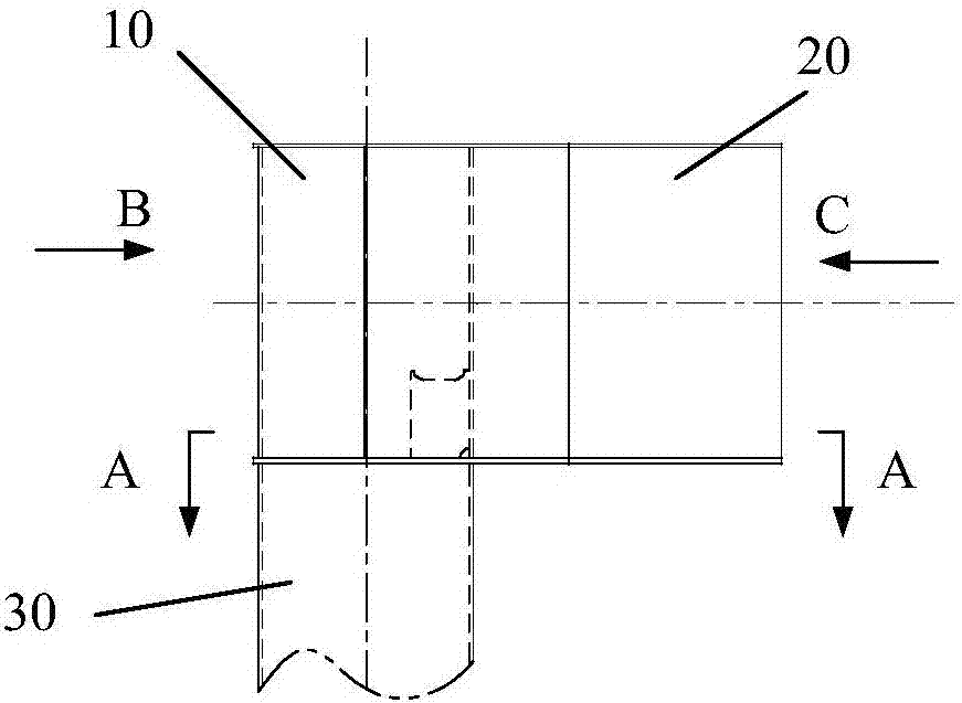
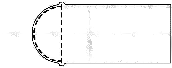
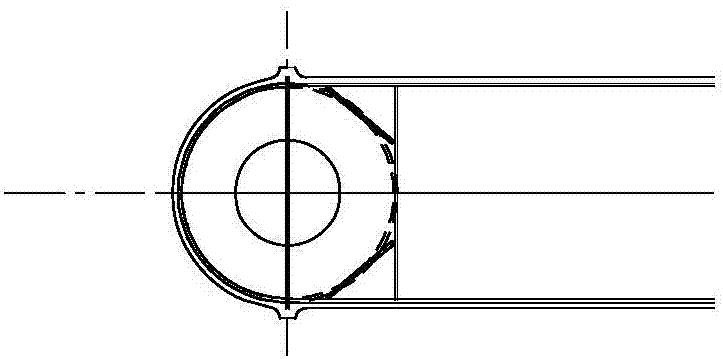
The invention provides a round joint used for a cylinder and a box beam. The round joint comprises a semicircular pipe short column, a hole-formed flange plate, a top cover plate, a U-shaped flange plate, webs, a transverse bar and force transmitting half bars. The hole-formed flange plate is arranged at the lower end of the semicircular pipe short column; the top cover plate is arranged at the upper end of the semicircular pipe short column; the U-shaped flange plate is arranged on the surface of the semicircular pipe short column; the lower edges of the webs are connected with the hole-formed flange plate, the upper edges of the webs are connected with the top cover plate, and the height of each web is equal to that of the semicircular pipe short column; the transverse bar is arranged parallel to the height direction of the semicircular pipe short column and is tangent to the circular ring extension line of the semicircular pipe column, the upper end of the transverse bar is connected with the top cover plate, and the lower end of the transverse bar is connected with the hole-formed flange plate; the lower edges of the force transmitting half bars are connected with the hole-formed flange plate, the two side edges of each force transmitting half bar are connected with the corresponding web and the transverse bar, and the upper ends of the force transmitting half bars are free. The manufacturing process of the round joint is simple and convenient to carry out, the joint from the cylinder to the box beam shows the round characteristic when being observed from the side face and the top of the joint, and thus the joint is different from an angular joint applied in the prior art.

Description

technical field [0001] The invention relates to the field of columns and box girders, in particular to a rounded joint for columns and box girders, which is mainly used in large-scale steel structure products. Background technique [0002] In large-scale steel structure products, columns and beams of large-scale steel structures are usually used as skeletons and are important stress-bearing members. The column mainly bears the axial pressure. Considering the isotropic characteristics, the column is often designed as a circular tube. For beams, concentrated loads or distributed loads on them usually generate large bending stresses, and are preferably designed as members of box-shaped sections. [0003] The connection between columns and beams of different cross-sections is relatively complicated. At present, flange plates and rectangular cross-section ribs are mostly used. The connection joints are more square, with sharp edges and corners, more ribs, and uneven force. Con...

Claims


Application Information

Patent Timeline
Patent Type & Authority Applications(China)
IPC IPC(8): E04B1/24E04B1/58
CPCE04B1/2403E04B2001/2472E04B2001/246
Inventor 罗磊曾鹏张明海李义明
Owner SHANGHAI ZHENHUA HEAVY IND
Learn More