
Brake structure of chain saw and chain saw

A chain saw and brake technology, applied in the field of chain saw braking, can solve the problems of complexity, the overall structure of the chain saw brake device is complicated, and achieve the effect of solving internal space problems, wide market application and promotion prospects, and simple structure.

Pending Publication Date: 2017-12-15
ZHEJIANG LERA NEW ENERGY POWER TECH CO LTD
View PDF9 Cites 2 Cited by
  • Summary
  • Abstract
  • Description
  • Claims
  • Application Information

AI Technical Summary

Problems solved by technology

[0002] In the prior art, the braking structure of the chainsaw generally adopts a relatively complex compression spring type integral braking structure, and someone has designed a chainsaw braking device such as the patent No. CN203592525U. When moving, the handle moves and drives the connecting rod structure to pull the brake band on the runner. The overall structure of the chainsaw brake device is still relatively complicated. The function of the spring in this device is to reset, and the braking power element of this device is a relatively complicated connecting rod structure.

Method used


Image

  • Brake structure of chain saw and chain saw
  • Brake structure of chain saw and chain saw
  • Brake structure of chain saw and chain saw

Examples


Embodiment Construction

[0024] The following are specific embodiments of the present invention and in conjunction with the accompanying drawings, the technical solutions of the present invention are further described, but the present invention is not limited to these embodiments.

[0025] Combine below Figure 1 to Figure 4 The technical solution provided by the present invention is described in more detail.

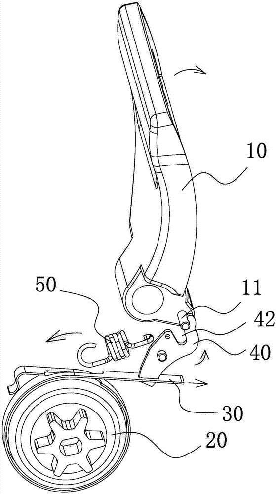
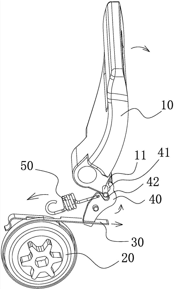
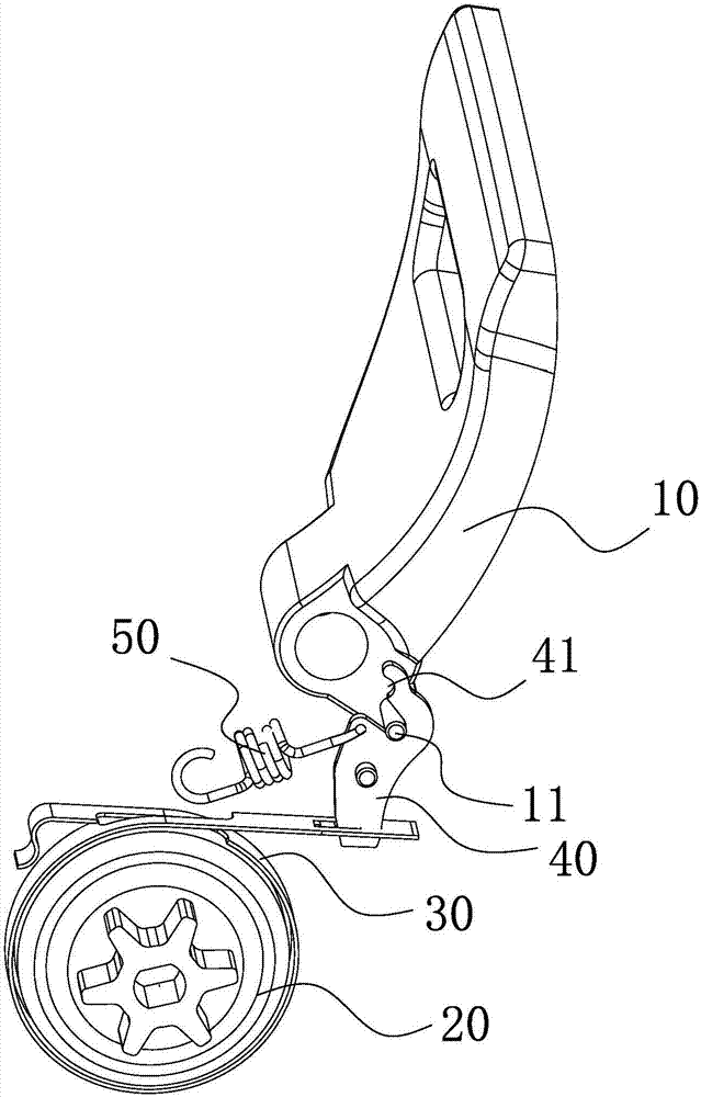
[0026] Such as Figure 1 to Figure 3 As shown, the brake structure of this chain saw includes:

[0027] Chainsaw frame (not shown in the figure);

[0028] The protective plate 10 is hinged on the chainsaw frame and the lower end thereof is provided with a limit column 11;

[0029] The brake disc 20 is tightly surrounded by a brake steel belt 30 on the periphery of the brake disc 20;

[0030] Brake 40, the middle of which is hinged on the chainsaw frame, the lower end of the brake 40 is connected with the brake steel belt 30, and the upper end is provided with a limit groove 41 adapted to th...


PUM


Abstract

The invention provides a brake structure of a chain saw. The brake structure of the chain saw comprises a chain saw rack, a brake disc, a protective plate, a brake part and a brake tension spring; a brake steel belt is closely arranged at the periphery of the brake disc in a surrounding manner; the protective plate is hinged to the chain saw rack, and the lower end of the protective plate is provided with a limiting column; the middle of the brake part is hinged to the chain saw rack, the lower end of the brake part is connected with the brake steel belt, and the upper end of the brake part is provided with a limiting groove matched with the limiting column and a brake gap located on the side, close to the brake steel belt, of the limiting groove; the brake tension spring is connected between the brake part and the chain saw rack, and when the chain saw is in a normal working state, the brake tension spring is in a tensional state, and the limiting column is arranged in the limiting groove. The brake structure of the chain saw has the advantages of being more simple in structure and reliable in work.

Description

technical field [0001] The invention belongs to the technical field of chain saw braking, and relates to a chain saw braking structure and the chain saw. Background technique [0002] In the prior art, the braking structure of the chainsaw generally adopts a relatively complex compression spring type integral braking structure, and someone has designed a chainsaw braking device such as the patent No. CN203592525U. When moving, the handle moves and drives the connecting rod structure to pull the brake band on the runner. The overall structure of the chainsaw brake device is still relatively complicated. The effect that spring plays in this device is to reset, and the braking power element of this device is to be provided with comparatively complicated connecting rod structure. [0003] In this regard, it is also necessary to design a brake structure of a chain saw with a simpler structure and reliable operation. Contents of the invention [0004] The object of the present...

Claims


Application Information

Patent Timeline
Patent Type & Authority Applications(China)
IPC IPC(8): B23Q5/04B23Q5/20B23D57/02B27B17/08
CPCB23D57/02B23Q5/04B23Q5/20B27B17/083
Inventor 李斌
Owner ZHEJIANG LERA NEW ENERGY POWER TECH CO LTD
Learn More