Inner groove machining device for lathe

A technology of processing device and inner groove, applied in metal processing equipment, tool holder, turning equipment, etc., can solve the problem of easy chattering, poor surface roughness of groove bottom, difficult control of groove radial size and axial positioning size And other issues

Active Publication Date: 2017-12-15
广州市新帅机械制造有限公司
View PDF5 Cites 6 Cited by
  • Summary
  • Abstract
  • Description
  • Claims
  • Application Information

AI Technical Summary

Problems solved by technology

[0002] The groove processing of pipe fittings or inner holes generally adopts the boring processing method in the process. Since the boring tool is supported by a cantilever, the greater the extension length, the worse the rigidity. The surface roughness is poor. In addition, the radial dimension and axial positioning dimension of the groove are not easy to control during boring

Method used


Image

  • Inner groove machining device for lathe
  • Inner groove machining device for lathe
  • Inner groove machining device for lathe

Examples


Embodiment Construction

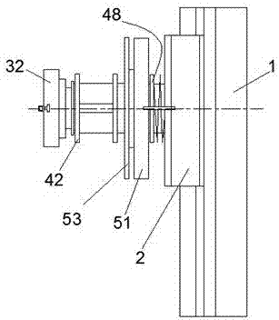
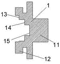
[0029] Such as Figure 1-Figure 8 As shown, an inner groove processing device for a lathe according to the present invention includes a clamping part 1, a body 2, a groove depth control device, an axial positioning size control device and a clamping device. The clamping part 1 is left There is a long rectangular convex strip 11 on the side, a rectangular guide rail convex strip 12 in the front and rear directions is provided on the upper and lower surfaces of the right side, and a front and rear direction is provided in the middle part of the right side. The right side of the body 2 is provided with a guide rail groove 21 in the front and rear direction, which forms a sliding fit with the rectangular guide rail protruding strip 12, and is aligned with the guide rail groove 21 up and down and near the front end. There is a first through hole 22 in the left and right direction, a keyway 24 for installing a guide flat key is arranged above the first through hole 22, and a counter...


PUM


Abstract

The invention discloses an inner groove machining device for a lathe. The inner groove machining device comprises a clamping piece, a body, a groove depth control device, an axial positioning dimension control device and a clamping device. A long rectangular raised strip is arranged on the left side of the clamping piece, and rectangular guide rail raised strips in the forward-backward direction are arranged on the upper surface and the lower surface of the right side of the clamping piece correspondingly; a guide rail groove slidably matched with the rectangular guide rail raised strips is formed in the right side of the body in the forward-backward direction; the groove depth control device is mounted on the left side of the body and rightwards penetrates through a first through hole to finally stretch into a combined groove in the middle of the right side face of the clamping piece; the clamping device is mounted in the position, located on the left side of the body, of the groove depth control device; and the axial positioning dimension control device is mounted on the clamping device. The dimension is controlled conveniently, operation is convenient and rapid, the machining precision can be guaranteed, and additionally, the machining efficiency can be improved.

Description

technical field [0001] The invention relates to the technical field of mechanical manufacturing, in particular to an inner groove processing device for a lathe. Background technique [0002] The groove processing of pipe fittings or inner holes generally adopts the boring processing method in the process. Since the boring tool is supported by a cantilever, the greater the extension length, the worse the rigidity. The surface roughness is poor. In addition, the radial dimension and axial positioning dimension of the groove are not easy to control during boring. Contents of the invention [0003] The technical problem to be solved by the present invention is to provide an inner groove processing device for a lathe, which can solve the above-mentioned problems in the prior art. [0004] The present invention is achieved through the following technical solutions: an inner groove processing device for a lathe of the present invention, including a clamping piece, a body, a groo...

Claims


Application Information

Patent Timeline
Patent Type & Authority Applications(China)
IPC IPC(8): B23B5/00B23B29/12
CPCB23B5/00B23B29/12
Inventor 汪任斌
Owner 广州市新帅机械制造有限公司
Why Eureka
Try Eureka