A small-current ground fault isolation method for distribution network based on area agent
A low-current grounding and regional proxy technology, applied in electrical components, emergency protection circuit devices, etc., can solve the problems of high failure rate of communication network, short life of backup power supply, unsatisfactory operation effect, etc., to achieve wide adaptability, guarantee Quickness and selectivity, the effect of improving power supply reliability
- Summary
- Abstract
- Description
- Claims
- Application Information
AI Technical Summary
Problems solved by technology
Method used
Image
Examples
Embodiment 1
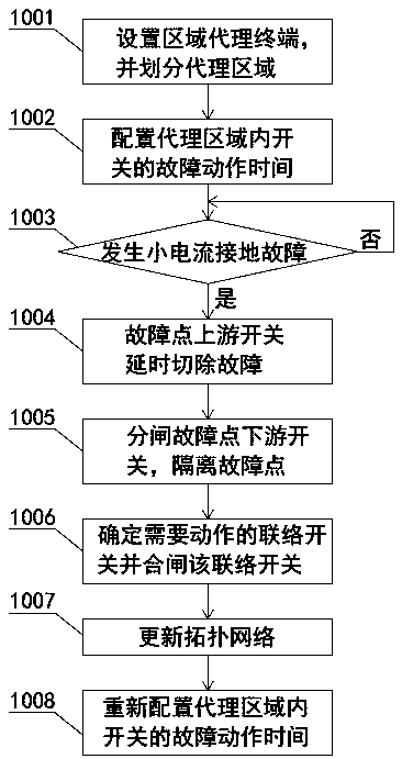
[0041] Such as figure 1 As shown, a small current ground fault isolation method of distribution network based on regional agent includes the following steps:
[0042] Step 1001, setting up regional agent terminals and dividing agent regions;
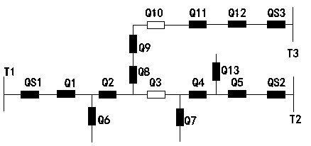
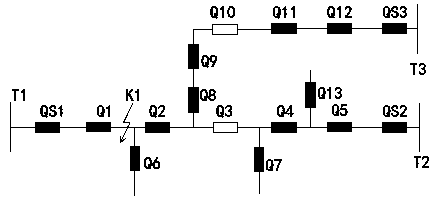
[0043] In this embodiment, taking the overhead line network as an example, in such as figure 2 The overhead line network shown has three power sources: power source T1, power source T2 and power source T3, and power outlet switches: outlet switch QS1~outlet switch QS3, outlet switch QS1~outlet switch QS3 are respectively connected to power source T1 and power source T2 And the corresponding connection of the power supply T3. Between the outlet switch QS1 and the outlet switch QS2, there are five section switches connected at one time: section switch Q1~section switch Q5, among which section switch Q3 is defined as a tie switch. Outlet switch QS3 is connected with five section switches in sequence: section switch Q12~section switch Q8...
Embodiment 2
[0072] In this embodiment, the initial state of the distribution network and figure 2 The distribution network shown is the same, assuming that the fault point K2 occurs in the agent area represented by the outlet switch QS3, specifically between the section switch Q5 and the outlet switch QS2, as shown in Figure 5 shown.
[0073] When the fault K2 occurs, the outgoing line switch QS2 judges that the transient reactive power is negative, that is, the outgoing line switch QS2 is located upstream of the fault point K2, then the outgoing line switch QS2 should be turned off, and when the configured action time is reached, the outgoing line The switch QS2 is turned off, and an instruction is issued to turn off the section switch Q5 downstream of the fault point K2, so as to realize the isolation of the fault section, such as Figure 6 shown.
[0074] Then the outgoing line switch QS2 compares the spare capacity of the tie switch Q3 and the tie switch Q10, assuming that the spa...
Embodiment 3
[0078] In this embodiment, the initial state of the distribution network and figure 2 The distribution network shown is the same, assuming that the fault point K3 occurs in the agent area represented by the outlet switch QS2, specifically between the section switch Q11 and the section switch Q12, as shown in Figure 7 shown.
[0079]When the fault K3 occurs, the outlet switch QS3 and the section switch Q12 judge that the transient reactive power is negative, that is, the outlet switch QS3 and the section switch Q12 are located upstream of the fault point K2, then the outlet switch QS2 and the section switch Q12 should be disconnected. When the configured action time is reached, the segment switch Q12 is first disconnected. After the segment switch Q12 operates, the zero-sequence voltage detected by the outlet switch QS3 disappears, and the outlet switch QS3 does not need to delay action, and the outlet After the switch QS3 receives the action information of the sub-section s...
PUM
 Abstract
Description
Claims
Application Information
 - R&D
- Intellectual Property
- Life Sciences
- Materials
- Tech Scout
- Unparalleled Data Quality
- Higher Quality Content
- 60% Fewer Hallucinations
Browse by: Latest US Patents, China's latest patents, Technical Efficacy Thesaurus, Application Domain, Technology Topic, Popular Technical Reports.
© 2025 PatSnap. All rights reserved.Legal|Privacy policy|Modern Slavery Act Transparency Statement|Sitemap|About US| Contact US: help@patsnap.com


