
A climatic environment chamber for building envelope thermal performance testing

A technology of building envelope structure and thermal performance, applied in the field of climate environment chamber, can solve the problems that it is difficult to truly reflect the outdoor environmental conditions, and the comprehensive simulation of outdoor climate conditions has not been realized.

Active Publication Date: 2017-12-12
SHANGHAI CONSTRUCTION GROUP
View PDF9 Cites 20 Cited by
  • Summary
  • Abstract
  • Description
  • Claims
  • Application Information

AI Technical Summary

Problems solved by technology

[0004] The application of the existing artificial climate environment chamber is mostly concentrated in the field of indoor environment detection, which is used for the research on the release of chemical pollutants from indoor building materials and articles, and all of them are single or combined simulations of outdoor climate parameters, that is, single simulation Temperature, relative humidity, solar radiation intensity, wind speed, wind direction or combined simulation of temperature and humidity, wind speed and wind direction, etc., without comprehensive simulation of outdoor climate conditions (temperature, relative humidity, solar radiation intensity, wind speed, wind direction), it is difficult to truly reflect the outdoor environmental conditions

Method used


Image

  • A climatic environment chamber for building envelope thermal performance testing
  • A climatic environment chamber for building envelope thermal performance testing
  • A climatic environment chamber for building envelope thermal performance testing

Examples


Embodiment Construction

[0039] In order to make the above objects, features and advantages of the present invention more comprehensible, the present invention will be further described in detail below in conjunction with the accompanying drawings and specific embodiments.

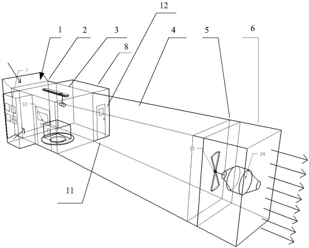
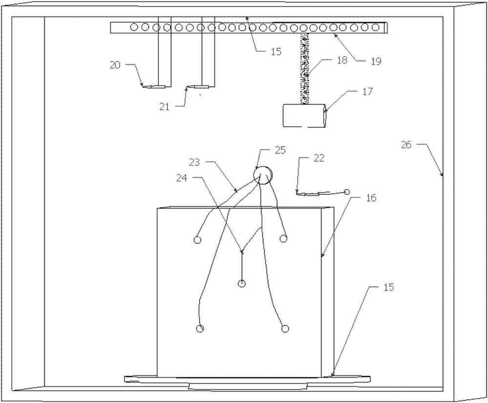
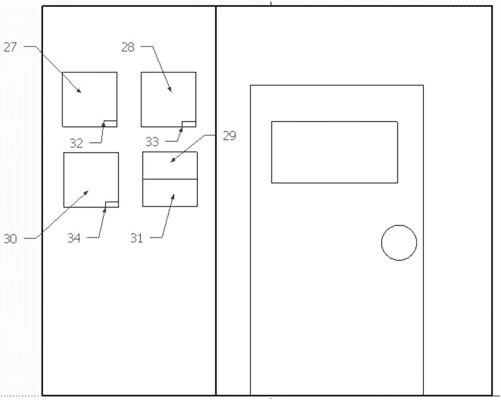
[0040] Such as Figure 1~6 As shown, the present invention provides a kind of climatic environment chamber that is used for the thermal performance test of building envelope structure, comprises generation chamber, the control chamber and the acquisition chamber adjacent to generation chamber respectively, wherein,

[0041] The occurrence chamber is used to provide the outdoor climate environment of temperature, relative humidity, wind speed and direction, and solar radiation intensity for the building scale model of the building envelope in the test chamber. , test chamber 3, diffuser section 4, fan section 5 and motor section 6;

[0042] Control cabin 7, is used for controlling the temperature in the test cabin 3, relative humi...


PUM


Abstract

The invention provides a climatic environment chamber for building envelope thermal performance testing. The climatic environment chamber comprises a generating chamber, a control chamber and a collection chamber, wherein the control chamber and the collection chamber are adjacent to the generating chamber. The generating chamber is used for providing an outdoor climatic environment in terms of temperature, relative humidity, wind speed and direction and solar radiation intensity for a building scale model of a building envelope in a test chamber. The generating chamber comprises an air accumulation section, an air processing section, the test chamber, a diffusion section, a fan section and a motor section, which are connected successively. The control chamber is used for controlling the temperature, relative humidity, wind speed and direction and solar radiation intensity in the test chamber. The collection chamber is used for collecting thermal performance data of the building scale model in the test chamber and displaying and outputting the thermal performance data after processing. The chamber can comprehensively simulate outdoor climatic conditions and test the influence of outdoor climatic conditions on the thermal performance of a building envelope.

Description

technical field [0001] The invention relates to a climate environment chamber used for thermal performance testing of building enclosure structures. Background technique [0002] Building energy consumption has accounted for more than 20% of the total energy consumption of the society, becoming one of the three major energy consumption alongside industrial energy consumption and transportation energy consumption, and it has risen sharply with the improvement of the total number of buildings and people's living standards. Among them, the heat consumption of the envelope structure accounts for more than 70% of the energy consumption of the entire building, so the thermal performance of the envelope structure is the decisive factor affecting the energy consumption of the building. With the continuous development of building energy conservation work in our country, the design standards of building energy conservation continue to improve, and the outdoor and changeable weather co...

Claims


Application Information

Patent Timeline
IPC IPC(8): G01M99/00G01N25/20
CPCG01M99/002G01N25/20
Inventor 沈丹丹黄玉林贾珍
Owner SHANGHAI CONSTRUCTION GROUP
Learn More