
Guide wire and preparation method thereof

A guide wire and core wire technology, applied in the direction of catheters, guide wires, medical science, etc., can solve the problems of transmission, guide wire torque, torque loss, cross-sectional area reduction of the head end core wire, etc., to achieve good lubricity and Tracking performance, good anti-deformation ability, and effects of excellent anti-deformation characteristics

Inactive Publication Date: 2017-12-12
APT MEDICAL HUNAN INC
View PDF8 Cites 9 Cited by
  • Summary
  • Abstract
  • Description
  • Claims
  • Application Information

AI Technical Summary

Problems solved by technology

[0003] The existing guide wire is mainly composed of a core wire, a sheath, and a coating. In order to ensure the rigidity of the proximal end of the guide wire, increase the flexibility of the distal end (head end) and facilitate the passage of tortuous blood vessels, the overall diameter of the core wire is from the proximal end to the The middle section gradually decreases from the distal end, but the reduction in the diameter of the core wire can make the head end softer, but at the same time greatly reduces the cross-sectional area of ​​the core wire at the head end, resulting in a serious loss of torsion and torque of the guide wire. When rotating the proximal end of the guidewire, the torque cannot be transferred 1:1
The torque is accumulated somewhere in the distal end. When the guide wire continues to rotate, the torque is released suddenly, causing the distal end of the guide wire to jump and flick, which affects the control of the direction of the distal end of the guide wire in the blood vessel.
[0004] Another important performance of the guide wire is the ability to maintain integrity during the manipulation process. In clinical applications, the guide wire is easy to get stuck in the stenosis of the blood vessel or other places. At this time, it is generally necessary to pull the proximal end of the guide wire to make it safely withdrawn. If the anti-deformation ability of the guide wire is insufficient, it is easy to cause the head end to be elongated, deformed or broken, which will affect the safety of the operation

Method used


Image

  • Guide wire and preparation method thereof
  • Guide wire and preparation method thereof
  • Guide wire and preparation method thereof

Examples


Embodiment Construction

[0035] In order to enable those skilled in the art to better understand the technical solutions in the present application, the technical solutions in the embodiments of the present application will be clearly and completely described below in conjunction with the drawings in the embodiments of the present application. Obviously, the described The embodiments are only some of the embodiments of the present application, but not all of them. Based on the embodiments in this application, all other embodiments obtained by persons of ordinary skill in the art without creative efforts shall fall within the scope of protection of this application.

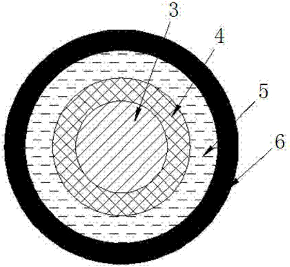
[0036] please if Figure 1 to Figure 3 As shown, the embodiment of the present invention provides a guide wire, including a distal end 1, a proximal end 2, and a core wire 3, the core wire 3 is arranged in the guide wire, and is connected from the proximal end 2 of the guide wire. Extending to the distal end 1 , the head end of the core ...


PUM

PropertyMeasurementUnit
lengthaaaaaaaaaa
diameteraaaaaaaaaa

Abstract

The invention discloses a guide wire. The guide wire comprises a far end (1), a near end (2) and a core wire (3), the core wire (3) is arranged in the guide wire and extends to the far end (1) from the near end (2) of the guide wire, and a safety net (4) is arranged at the head end, located at the far end (1), of the core wire (3) and fixedly connected with the head end. The invention further provides a preparation method of the guide wire. Accordingly, by additionally arranging the safety net at the head end, located at the far end, of the core wire, the cross section area of the guide wire far end is increased, the loss of guide wire toque force and torque transmission is reduced, and the flexibility and deformation resistance of the guide wire far end are guaranteed while the drifting phenomenon is eliminated.

Description

technical field [0001] The present application relates to the technical field of medical devices, in particular to a guide wire for intravascular interventional therapy and a preparation method thereof. Background technique [0002] Guide wires are widely used in interventional procedures, such as percutaneous transluminal coronary angioplasty (PTCA) or percutaneous transluminal angioplasty (PTA). In the process of interventional diagnosis and treatment, the guide wire provides the basic track for interventional devices such as catheters, stents, and balloons, and is an indispensable accessory product in interventional operations. For example, during coronary stent implantation, the guide wire first enters the femoral artery, and then the proximal end of the guide wire is controlled to drive the head end of the guide wire to rotate, so that the guide wire advances in each branch of the coronary artery in a predetermined direction. When the guide wire reaches the target site...

Claims


Application Information

Patent Timeline
Patent Type & Authority Applications(China)
IPC IPC(8): A61M25/09A61B17/00
CPCA61B17/00234A61M25/0009A61M25/0021A61M25/0045A61M25/005A61M25/0054A61M25/0068A61M25/09A61M2025/0008A61M2025/0046A61M2025/0063A61M2025/09108A61M2025/09133A61M2025/09166A61M2025/09175A61M2025/09083
Inventor 黄河洪浪江洪成正辉易沛林彭传东
Owner APT MEDICAL HUNAN INC
Learn More