
A method for real-time observation of base station equipment data indicators

A technology of base station equipment and real-time observation, applied in the field of communication, can solve the problems of many indicators of query, inconvenient observation results, and difficult analysis of indicators, etc., to achieve the effect of easy problem discovery, saving manpower and material resources, and significant market value.

Active Publication Date: 2020-04-10
WUHAN HONGXIN TELECOMM TECH CO LTD
View PDF5 Cites 0 Cited by
  • Summary
  • Abstract
  • Description
  • Claims
  • Application Information

AI Technical Summary

Problems solved by technology

[0003] For the operation and maintenance personnel of base station equipment, in the process of equipment operation and maintenance, it is even more necessary to know the operation status of the equipment in real time. One of the existing methods is to remind the operation and maintenance personnel by reporting an alarm when the equipment has an operation error. The disadvantage of this method is that it can only detect the faults of equipment operation, but it is impossible to grasp the various performance indicators and operating status of the equipment in real time.
Another method is to query some performance indicators. The disadvantage of this method is that generally only the instantaneous value of a certain time can be queried, and it is impossible to form an intuitive impression of the continuous changes of the indicators over a period of time, and it is inconvenient to quickly obtain observation results. , and there are so many indicators that need to be queried, the query is very inconvenient, and the correlation between indicators cannot be obtained, so it is very difficult to analyze the indicators

Method used

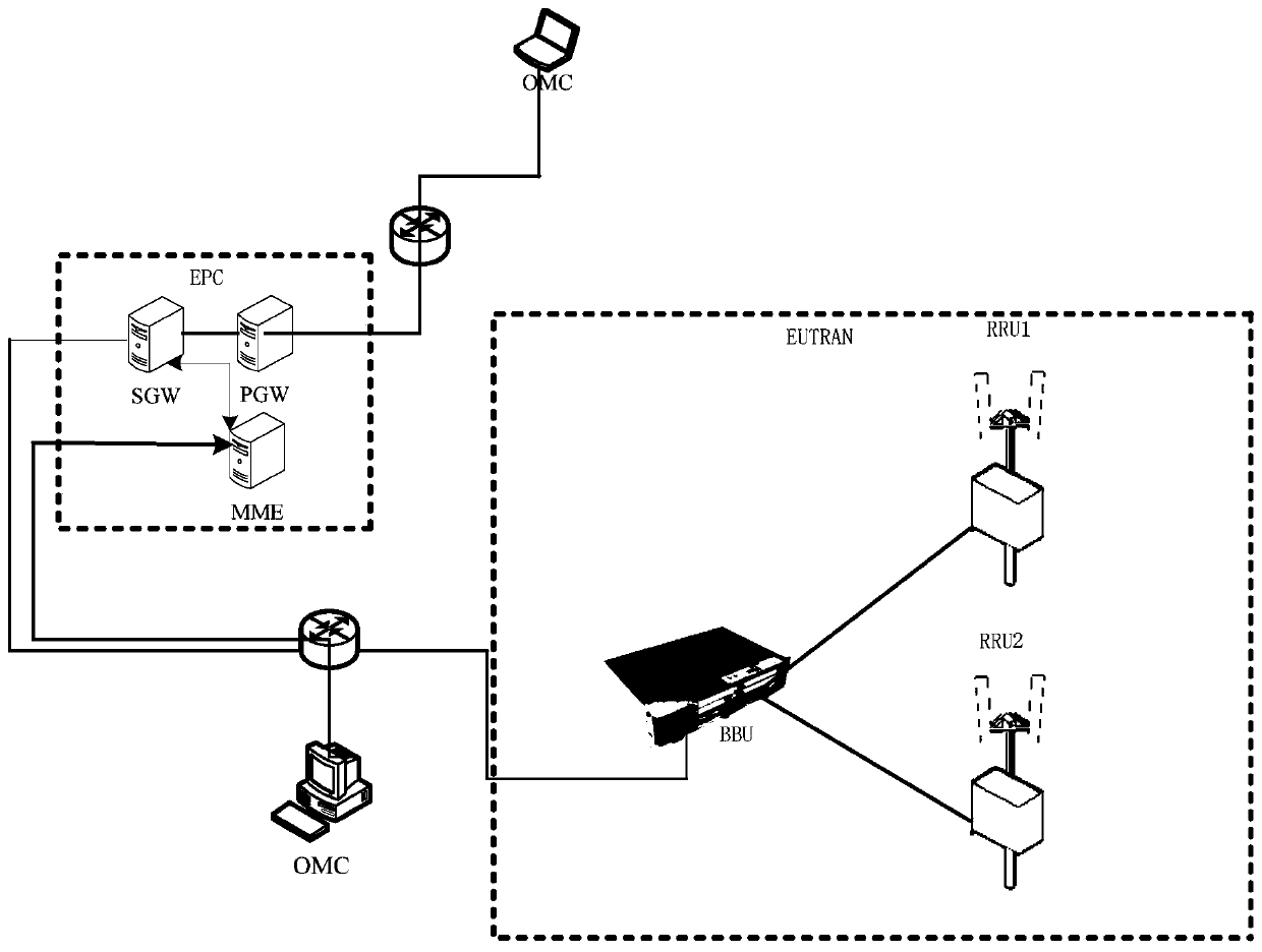

Image

  • A method for real-time observation of base station equipment data indicators
  • A method for real-time observation of base station equipment data indicators
  • A method for real-time observation of base station equipment data indicators

Examples


Embodiment Construction

[0033] The technical solution of the present invention will be described in detail below in conjunction with the drawings and embodiments.

[0034] In order to make it easier for those skilled in the art to understand and implement the present invention, the present invention will be further described in detail below in conjunction with the accompanying drawings and specific embodiments.

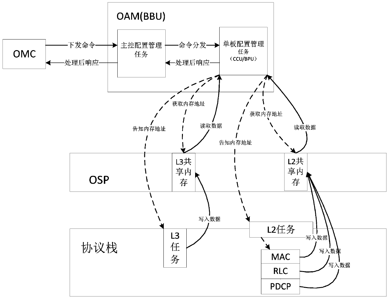
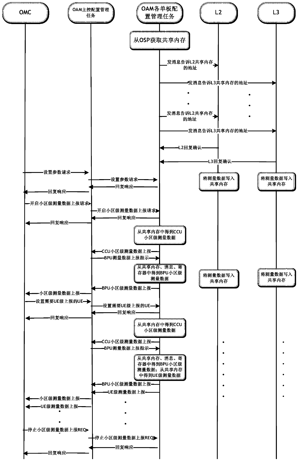
[0035] The core objective of this method is to provide a complete set of solutions for real-time observation of cell-level and UE-level data index information on operating equipment in order to facilitate development and operation and maintenance personnel to grasp the status of base station equipment in real time. In this solution, L2 / L3 (layer L2 and layer L3) provides the basic data during equipment operation, and OAM extracts and processes the data, and then reports it to OMC at regular intervals. The viewing angle and UE viewing angle are presented to the user for viewing. Support the ...


PUM


Abstract

The invention provides a method for observing a base station equipment data index in real time. The method comprises the steps of acquiring a shared memory space by an OAM of a base station from an OSP in initialization, transmitting information to a layer L2 and a layer L3 for notifying a shared memory address; filling various parameter values of a working cell and various parameter values of active UE in the shared memory by the layer L2 and the layer L3; after the OAM receives a measurement reporting activation instruction of the OMC, extracting required measuring items, generating reporting data from the acquired basic data through calculation, performing feedback of the reporting data to the OMC, and performing graphical displaying by the OMC according to the reporting data. The method can facilitate real-time mastering of base station equipment in operation by developing and operation maintenance personnel. A whole set of solution for observing cell-grade and UE-grade data index information in the operation equipment is supplied. Furthermore IMSI and bitmap testing by the OAM is supported. High consistency and high accuracy of the UE data which are supplied from the L2 / L3 are ensured.

Description

technical field [0001] The invention belongs to the communication field and relates to a method for real-time observation of base station equipment data indicators. Background technique [0002] For the developers of base station equipment, in the process of function development and debugging, they often need to know the running status of the equipment in real time. The usual way is to add debugging logs to the code or capture data packets through the network to realize the purpose of monitoring the running status of the equipment. The disadvantage of this method is that the display is not intuitive, and useful data needs to be extracted from the vast log information and network data packets for analysis, which is inefficient. [0003] For the operation and maintenance personnel of base station equipment, in the process of equipment operation and maintenance, it is even more necessary to know the operation status of the equipment in real time. One of the existing methods is ...

Claims


Application Information

Patent Timeline
Patent Type & Authority Patents(China)
IPC IPC(8): H04W24/04H04W24/10
CPCH04W24/04H04W24/10
Inventor 曹凯
Owner WUHAN HONGXIN TELECOMM TECH CO LTD
Learn More