
Protective switch cabinet

A technology of switchgear and protective board, which is applied in substation/switch layout details, substation/switchgear cooling/ventilation, electrical components, etc. It can solve problems such as separation of different wiring slots, poor protection performance, and outer wall wear. , to achieve the effect of avoiding confusion, facilitating maintenance and reducing trouble

Inactive Publication Date: 2017-12-08
HEFEI HONGGUANG ELECTRIC CO LTD
View PDF5 Cites 1 Cited by
  • Summary
  • Abstract
  • Description
  • Claims
  • Application Information

AI Technical Summary

Problems solved by technology

[0003] The purpose of the present invention is to provide a protective switchgear to solve the problems of poor protective performance during use, inability to separate different wiring slots, and frequent wear and tear on the outer wall proposed in the background art

Method used


Image

  • Protective switch cabinet
  • Protective switch cabinet
  • Protective switch cabinet

Examples


Embodiment Construction

[0015] The following will clearly and completely describe the technical solutions in the embodiments of the present invention with reference to the accompanying drawings in the embodiments of the present invention. Obviously, the described embodiments are only some, not all, embodiments of the present invention. Based on the embodiments of the present invention, all other embodiments obtained by persons of ordinary skill in the art without making creative efforts belong to the protection scope of the present invention.

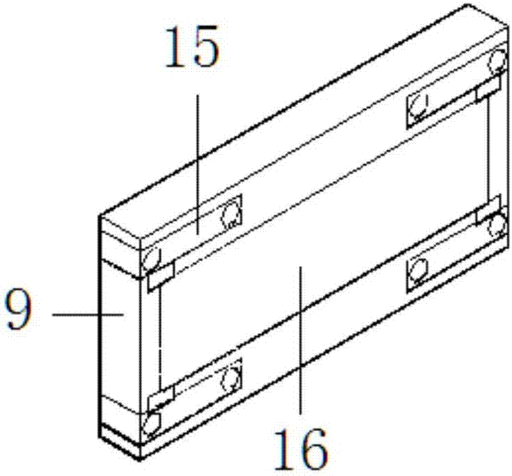
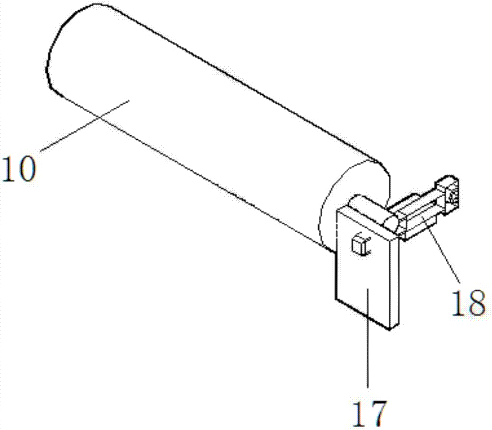
[0016] see Figure 1-3 , the present invention provides a technical solution: a protective switchgear, including a cabinet door 1, an observation window 2, a handle 3, a switchgear body 4, a recording board 5, a protective plate 6, a buffer column 7, a wear-resistant plate 8, Wiring groove 9, fixed rod 10, non-slip base 11, dust collection plate 12, isolation plate 13, suspension plate 14, fixed plate 15, heat conduction layer 16, limit plate 17 and fixing scr...


PUM


Abstract

A protective switch cabinet disclosed by the present invention comprises a cabinet door, a switch cabinet main body, buffer columns and a wear resistant plate. An observation window is arranged on the surface of the cabinet door, a handle is fixed at the edge of the cabinet door, and the switch cabinet main body is fixed at the inner side of the cabinet door. A recording plate is arranged at the top end of the switch cabinet main body, the buffer columns are embedded in the two sides of the top end of the switch cabinet main body, and the upper parts of the buffer columns are connected with a protective plate. The wear resistant plate is installed on the side surface of the switch cabinet main body, a fixing rod is arranged at the bottom side of the wear resistant plate, and the inner wall of the switch cabinet main body is fixed to a wiring groove. An anti-skid pedestal is arranged at the external bottom end of the switch cabinet main body, a hanging plate is embedded in the inner wall of the switch cabinet main body, a dust collecting plate is installed at the internal bottom end of the switch cabinet main body, and an isolating plate is arranged in the middle of the dust collecting plate. The protective switch cabinet can be protected by the protective plate installed at the top end, and can avoid the situation that the external objects drop down to damage the switch cabinet.

Description

technical field [0001] The invention relates to the technical field of switch cabinet devices, in particular to a protective switch cabinet. Background technique [0002] The switch cabinet is a kind of electrical equipment. The external line of the switch cabinet first enters the main control switch in the cabinet, and then enters the sub-control switch, and each branch is set according to its needs. Such as instruments, automatic controls, motor magnetic switches, various AC contactors, etc., some also have high-voltage room and low-voltage room switch cabinets, high-voltage busbars, such as power plants, etc. load shedding. The main function of switchgear is to switch, control and protect electrical equipment during the process of power generation, transmission, distribution and power conversion in the power system. The protection performance of the existing switchgear is not good during use, different wiring slots cannot be separated, and the outer wall is prone to mor...

Claims


Application Information

Patent Timeline
Patent Type & Authority Applications(China)
IPC IPC(8): H02B1/56H02B1/30
CPCH02B1/565H02B1/30
Inventor 薛传标
Owner HEFEI HONGGUANG ELECTRIC CO LTD
Learn More