
Double steam plate garment steamer nozzle

A steam plate and garment ironing technology, applied in the field of garment ironing machines, can solve problems such as inability to press clothes, decrease in efficiency, inconvenient use, etc., and achieve the effect of overcoming the tendency to flutter

Active Publication Date: 2019-08-09
苏州市海朋生活家电有限公司
View PDF5 Cites 0 Cited by
  • Summary
  • Abstract
  • Description
  • Claims
  • Application Information

AI Technical Summary

Problems solved by technology

[0002] When the hanging ironer is in use, the clothes to be ironed are suspended, which also brings about a problem. Due to the lack of effective support for the clothes, the clothes will float with a little force from the nozzle, which cannot be pressed on a flat ironing board. When ironing clothes, the efficiency is reduced, which brings inconvenience to use

Method used


Image

  • Double steam plate garment steamer nozzle
  • Double steam plate garment steamer nozzle
  • Double steam plate garment steamer nozzle

Examples


Embodiment 1

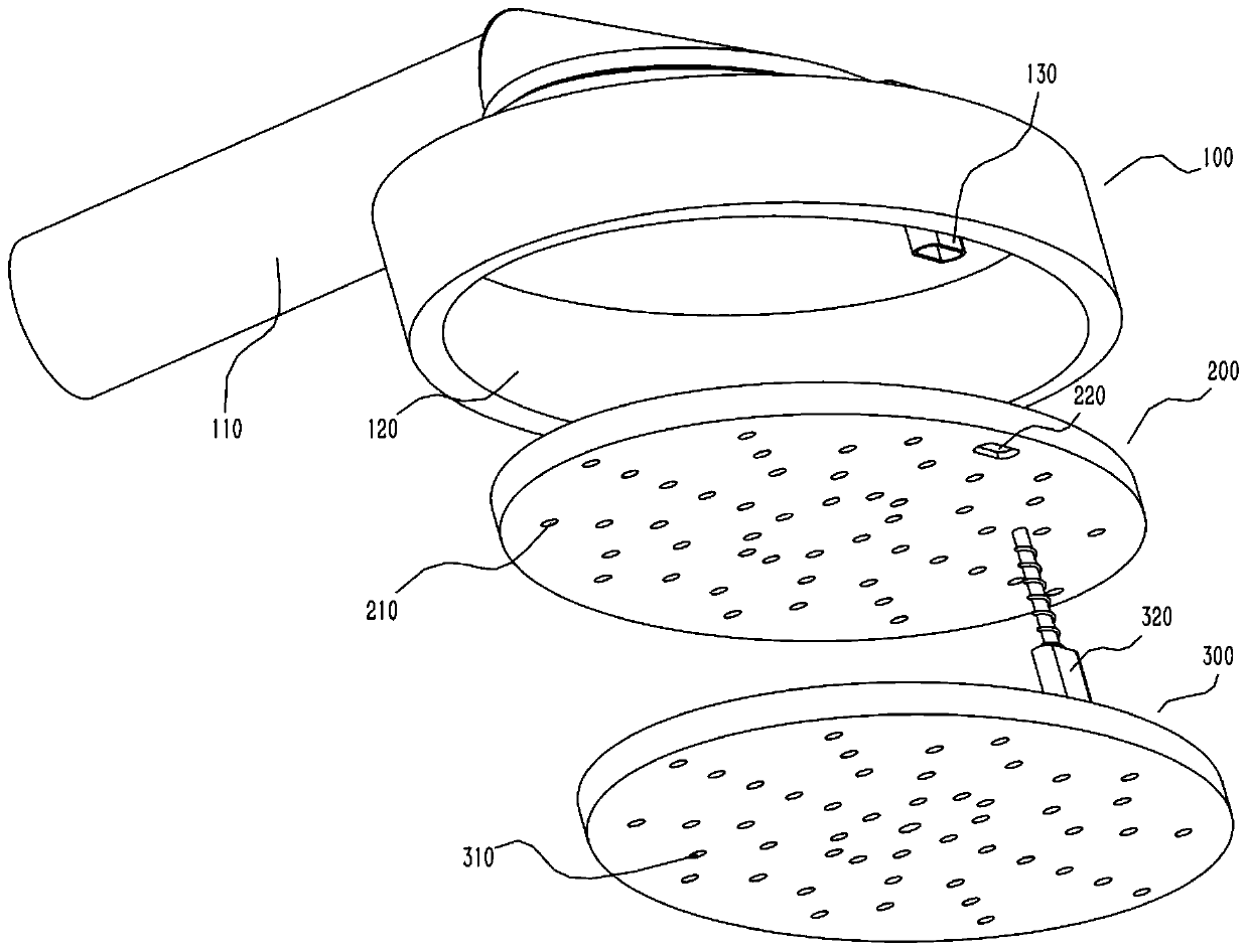
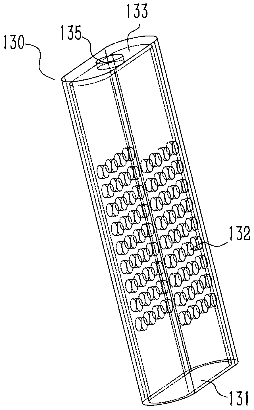
[0032] A spray head of a double steam plate garment ironing machine, comprising: a casing 100 with an air inlet pipe 110 on the upper part, a first cavity in the middle of the casing 100, and a first opening 120 at the lower part of the casing 100 , The air inlet duct 110 and the first opening 120 are both in communication with the first cavity, a sliding pipe 130 is vertically arranged at the lower part of the housing 100, and the first end 131 of the sliding pipe is connected to the first cavity. The cavities are connected, the pipe wall of the slide pipe 130 is provided with a number of vent holes 132, and the second end 133 of the slide pipe is closed; the upper steam plate 200 has a second cavity inside, and the upper steam plate 200 is parallel Is arranged in the first opening 120, the upper steam plate 200 is provided with a plurality of first through holes 210, the first through holes 210 are in communication with the second cavity, and the upper steam plate 200 is provi...

Embodiment 2

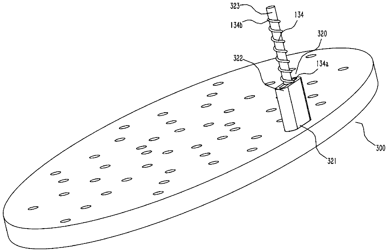
[0037] The slide tube 130 is provided with a first spring 134, the first end 134a of the first spring is fixedly connected to the second end 133 of the slide tube, and the second end 134b of the first spring is connected to the support tube 320 fixed connection. A button 323 is also connected to the second end 322 of the support tube, and the button 323 passes through the first spring 134 and protrudes from the second end 133 of the sliding tube. The second end 133 of the sliding tube is provided with a fourth through hole 135 for the button 323 to pass through. The button 323 is made of heat-insulating material to prevent users from being scalded. The first spring 134 is in a stretched state, so that the lower steam plate 300 always has the power to pull upward. By pressing the button 323, the lower steam plate 300 can be pressed down with the upper steam plate 200 to form a gap as needed, and ironing will be required. Put the clothes in the gap, release the button 323, the ...


PUM


Abstract

The invention relates to a nozzle of a double-steam-board garment steamer. The nozzle comprises a shell, an upper steam board and a lower steam board, wherein a gas inlet pipeline is arranged at the upper portion of the shell, a first cavity is formed in the middle of the shell, the lower portion of the shell is opened to form a first opening, a slide pipe is vertically arranged at the lower portion of the shell, a plurality of vent holes are formed in the pipe wall of the slide pipe, the second end of the slide pipe is closed, a second cavity is formed in the upper steam board, the upper steam board is arranged in the first opening in parallel, a plurality of first through holes are formed in the upper steam board and communicated with the second cavity, a second through hole is formed in the upper steam board, a third cavity is formed in the lower steam board, the lower steam board is arranged below the upper steam board in parallel, a plurality of third through holes are formed in the lower steam board, and a supporting pipe is vertically upwards arranged on the upper surface of the lower steam board. By arranging the movable upper steam board and the movable lower steam board, the effect of clamping and ironing clothes is realized.

Description

Technical field [0001] The invention relates to the field of garment ironing machines, in particular to a spray head of a double steam plate garment ironing machine. Background technique [0002] The garment ironing machine suspends the clothes that need to be ironed during use, which also brings about a problem. Due to the lack of effective support for the clothes, the clothes will float with the slightest force of the nozzle, and it cannot be pressed on a flat ironing board. Ironing clothes reduces the efficiency and brings inconvenience to use. Summary of the invention [0003] An object of the present invention is to solve at least the above-mentioned problems or deficiencies and provide at least the advantages described later. [0004] Another object of the present invention is to provide a spray head of a double steam plate garment ironing machine, which can achieve the effect of clamping clothes for ironing by arranging two movable upper and lower steam plates. [0005] To th...

Claims


Application Information

Patent Timeline
Patent Type & Authority Patents(China)
IPC IPC(8): D06F73/00
CPCD06F73/00
Inventor 陆苏忠
Owner 苏州市海朋生活家电有限公司
Learn More