Waste gas treatment equipment and equipment protection method

A waste gas treatment equipment and waste gas technology, applied in the field of environmental treatment, can solve problems such as large maintenance costs, electric leakage, easy oxidation of electronic components, etc., and achieve the effect of preventing water failure and high temperature explosion

Pending Publication Date: 2017-12-08
永康市广多环保设备科技有限公司
View PDF4 Cites 0 Cited by
  • Summary
  • Abstract
  • Description
  • Claims
  • Application Information

AI Technical Summary

Problems solved by technology

Furthermore, the low-temperature plasma workplace is electronically controlled. If the spray water in the early stage is not completely dried, then the electronic components are prone to oxidation or leakage in a humid environment for a long time, requiring frequent maintenance, which increases the maintenance cost greatly.

Method used


Image

  • Waste gas treatment equipment and equipment protection method
  • Waste gas treatment equipment and equipment protection method
  • Waste gas treatment equipment and equipment protection method

Examples


Embodiment 1

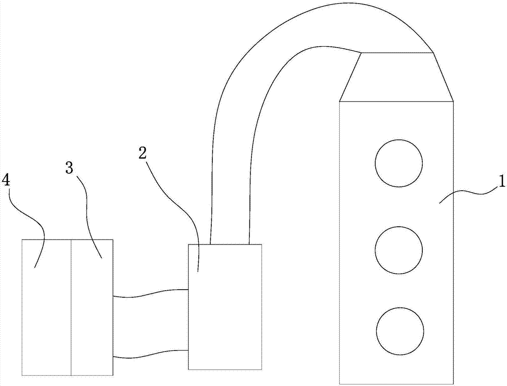
[0030] figure 1 Among them, the present invention comprises the spray tower 1 (prior art) that connects successively, throw away device, low-temperature plasma purifier 3, photo-oxygen catalytic purifier 4 (prior art), spray tower 1 preliminarily purifies waste gas, in The liquid medicine is sprayed in the tower to make it react with the mist of organic matter in the exhaust gas.

[0031] After preliminary purification, the exhaust gas is sucked out from the top of the tower, and enters the detachment device through the pipeline. The detachment device is a centrifugal fan 2, the inlet end of the centrifugal fan 2 is connected to the spray tower 1, and the outlet end is connected to the low temperature Plasma Purifier3.

[0032] The centrifugal fan 2 can dehydrate the exhaust gas from the spray tower 1, and centrifugally dry the water vapor and part of the unreacted organic mist in the exhaust gas, so that the exhaust gas can reach the standard dryness when it enters the low-t...

Embodiment 2

[0046] attached figure 1 It is a schematic diagram of the structure of the present invention, and the present invention includes a spray tower 1 (prior art), a spin-off device, a low-temperature plasma purifier 3, and a photo-oxygen catalytic purifier 4 (prior art) connected in sequence, and the spray tower 1 is preliminary To purify the exhaust gas, spray the potion in the tower to make it react with the organic mist in the exhaust gas.

[0047] After preliminary purification, the exhaust gas is sucked out from the top of the tower, and enters the detachment device through the pipeline. The detachment device is a centrifugal fan 2, the inlet end of the centrifugal fan 2 is connected to the spray tower 1, and the outlet end is connected to the low temperature Plasma Purifier3.

[0048] The centrifugal fan 2 can dehydrate the exhaust gas from the spray tower 1, and centrifugally dry the water vapor and part of the unreacted organic mist in the exhaust gas, so that the exhaust ...


PUM


Abstract

The invention provides waste gas treatment equipment and an equipment protection method and belongs to the field of environmental protection. The waste gas treatment equipment comprises a spraying tower, wherein the spraying tower is connected with a spinning device, the spinning device is connected with a photo-oxygen catalytic purifier and a low-temperature plasma purifier, waste gas sequentially passes through the spraying tower and the spinning device and enters the photo-oxygen catalytic purifier and the low-temperature plasma purifier, a discharging needle device, a spraying device, a temperature detecting device and a drying blower are arranged in the low-temperature plasma purifier and are all connected with a central control module, and the central control module controls the make and break of a power supply of the discharging needle device and the make and break of an electromagnetic valve of the spraying device. According to the waste gas treatment equipment and the equipment protection method, the low-temperature plasma purifier is effectively protected, a reaction process can be prevented from high-temperature explosion, and electronic components and devices are prevented from water-access failure; the equipment achieves the aims of automatic monitoring and one-key use.

Description

technical field [0001] The invention relates to the field of environmental treatment, in particular to waste gas treatment equipment and a protection method for the equipment. Background technique [0002] Industrial waste gas is one of the "three wastes", and its components mainly include various solid particles and harmful gases containing sulfur and toluene. The large amount of exhaust gas is not only the main cause of acid rain but also one of the causes of smog. Therefore, national policies and laws stipulate that industrial waste gas must be treated before it can be discharged into the atmosphere. In response to this regulation, many desulfurization, dust removal and purification equipment came into being. However, the exhaust gas produced by some industries has complex components and does not only contain several harmful substances. Therefore, it is often difficult to purify thoroughly during the purification process, resulting in unsatisfactory purification effects...

Claims


Application Information

Patent Timeline
Patent Type & Authority Applications(China)
IPC IPC(8): B01D53/32B01D53/75
CPCB01D53/32B01D53/75B01D2259/818
Inventor 胡汉斌
Owner 永康市广多环保设备科技有限公司
Why Eureka
Try Eureka