
High-precision pulse signal time difference measurement device and method

A pulse signal and measurement device technology, applied in the direction of pulse characteristic measurement, etc., can solve the difficult and high-precision test pulse signal time difference and other problems, and achieve the effect of eliminating the influence of precision and improving precision

Inactive Publication Date: 2017-12-05
UNIV OF ELECTRONICS SCI & TECH OF CHINA
View PDF8 Cites 7 Cited by
  • Summary
  • Abstract
  • Description
  • Claims
  • Application Information

AI Technical Summary

Problems solved by technology

[0004] The object of the present invention is to provide a high-precision pulse time difference measurement device and method, which can improve the accuracy of the signal time difference counting cycle, eliminate the influence of the accuracy of the reference clock signal, and solve the problem of difficult high-precision measurement of pulse signal time difference in the prior art question

Method used


Image

  • High-precision pulse signal time difference measurement device and method
  • High-precision pulse signal time difference measurement device and method

Examples


Embodiment Construction

[0042] All features disclosed in this specification, or steps in all methods or processes disclosed, may be combined in any manner, except for mutually exclusive features and / or steps.

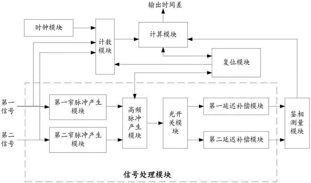
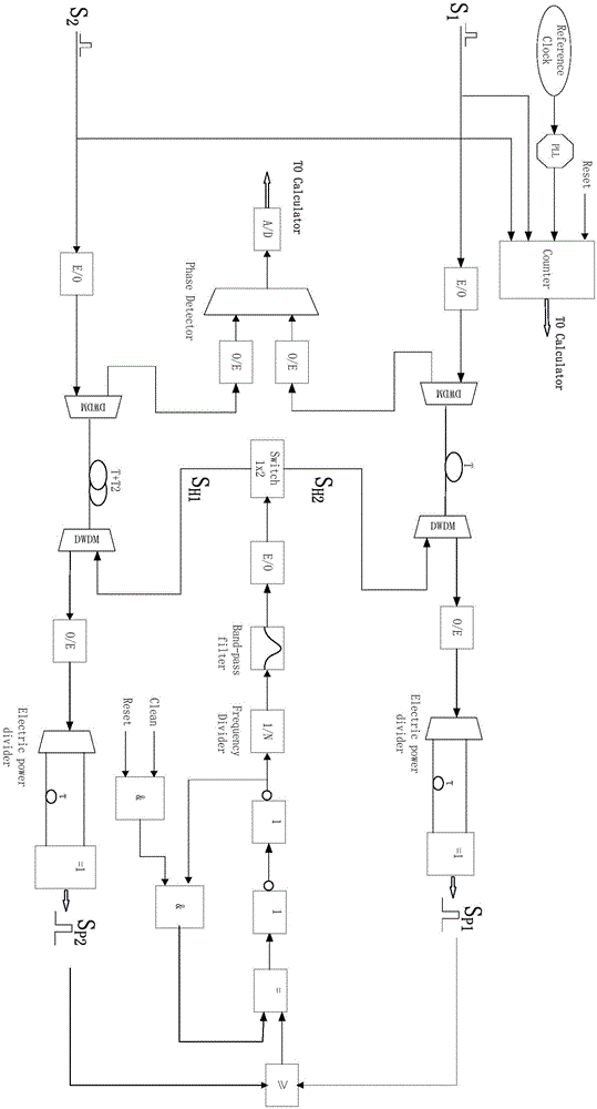
[0043] Combine below figure 1 , figure 2 The present invention will be described in detail.

[0044] A high-precision pulse signal time difference measuring device, comprising:

[0045] A signal processing module, configured to process the input first signal and the second signal into a first high-frequency sinusoidal observation signal and a second high-frequency sinusoidal observation signal with the same cycle and the same delay;

[0046]A clock module, configured to obtain a counting clock signal of the same period as the first high-frequency sinusoidal observation signal and the second high-frequency sinusoidal observation signal;

[0047] The counting module is connected to the signal processing module and the clock module, and is used to obtain the counting number Counter between th...


PUM


Abstract

The invention provides a high-precision pulse signal time difference measurement device, and the device comprises a signal processing module which is used for generating a high-frequency sinusoidal observed quantity signal, a clock module which is used for generating a signal with the same period as the high-frequency sinusoidal observed quantity signal, a counting module which is used for obtaining integral-multiple period time difference, a phase discrimination measurement module for obtaining the phase difference, a calculation module for calculating the time difference between a first signal and a second signal, and a resetting module which is used for enabling the device to be in an initial state. The invention also provides a method employing the above device. The method employs the optical signal and electric signal processing technology to process two input signals into two high-frequency sinusoidal observed quantity signals, and the two sinusoidal observed quantity signals are inputted to a phase discriminator for direct phase discrimination, so as to obtain the time difference which is less than one counting cycle, thereby eliminating the precision impact from a reference clock signal. When the counting clock with the same period with the high-frequency sinusoidal observed quantity signal is used for the timing of the integral-multiple periods, the precision of the signal time difference counting period is improved, and a problem that the high-precision testing of pulse signal time difference is difficult to achieve is solved.

Description

technical field [0001] The invention belongs to the technical field of signal time difference measurement, and in particular relates to a time difference measurement device and method for a high-precision clock pulse signal. Background technique [0002] High-precision clock synchronization is the basis for 5G networks, the Internet of Everything, and satellite navigation systems to achieve high-precision positioning. Achieving high-precision clock synchronization requires high-precision measurement of clock differences between nodes. Pulse signal time difference measurement technology provides a method that can meet the high precision measurement of time difference, and is an important determinant of high precision clock synchronization. [0003] Pulse signal time difference refers to the time difference between two pulse signals arriving at the observation point. Traditional methods use direct counting, capacitance integration, and time interpolation techniques. The dir...

Claims


Application Information

Patent Timeline
Patent Type & Authority Applications(China)
IPC IPC(8): G01R29/02
CPCG01R29/02
Inventor 苏君范志强张天航邱琪
Owner UNIV OF ELECTRONICS SCI & TECH OF CHINA
Learn More