
Post-optimized joint energy dissipation working body mould

An energy dissipation technology, energy dissipation technology, applied in water conservancy projects, sea area engineering, coastline protection, etc., can solve the uneconomical size of wide tail pier, large negative pressure value of overflow dam surface, cavitation cavitation damage of dam surface, etc. problems, to achieve the effect of long maintenance period and small size requirements

Inactive Publication Date: 2017-12-05
KUNMING UNIV OF SCI & TECH
View PDF3 Cites 4 Cited by
  • Summary
  • Abstract
  • Description
  • Claims
  • Application Information

AI Technical Summary

Problems solved by technology

However, the combination of wide tail pier and stilling basin for energy dissipation and scour prevention has a better energy dissipation effect, but the negative pressure on the overflow dam surface is relatively large, and cavitation and cavitation damage on the dam surface are prone to occur.
The cavitation and cavitation phenomenon on the overflow dam surface has been improved to a certain extent by using the combined energy dissipation of wide-end piers and energy-dissipating steps, but it is not suitable for high water head and large flow conditions or the size of wide-end pier is still large and uneconomical

Method used


Image

  • Post-optimized joint energy dissipation working body mould
  • Post-optimized joint energy dissipation working body mould

Examples


Embodiment 1

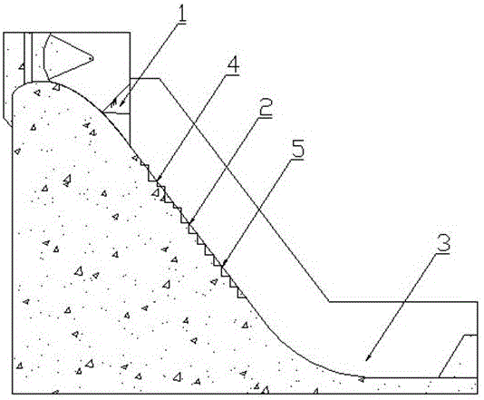
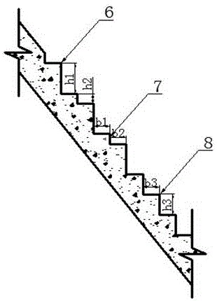
[0017] Embodiment 1: as Figure 1-2 As shown in Fig. 1, an optimized joint energy dissipation body shape, including wide tail pier 1, energy dissipation step 2, and stilling pool 3; wide tail pier 1 is located at the tail of the WES overflow dam face gate pier, and energy dissipation step 2 is located at the dam In the straight section of the overflow dam surface of the body WES, one end of the energy dissipation step 2 is connected to the wide end pier 1, and the other end of the energy dissipation step 2 is connected to the stilling pool 3 through an anti-arc section, and the energy dissipation step 2 includes the energy dissipation step transition section 4 , Energy dissipation step uniform section 5; energy dissipation step transition section 4 is located on the upper part of energy dissipation step uniform section 5, energy dissipation step transition section 4 is a combined step, the height h1 of step I6 is 1m, and the height h2 of step II7 is 1m. The width b1 of I6 is 1...

Embodiment 2

[0019] Embodiment 2: as Figure 1-2 As shown in Fig. 1, an optimized joint energy dissipation body shape, including wide tail pier 1, energy dissipation step 2, and stilling pool 3; wide tail pier 1 is located at the tail of the WES overflow dam face gate pier, and energy dissipation step 2 is located at the dam In the straight section of the overflow dam surface of the body WES, one end of the energy dissipation step 2 is connected to the wide end pier 1, and the other end of the energy dissipation step 2 is connected to the stilling pool 3 through an anti-arc section, and the energy dissipation step 2 includes the energy dissipation step transition section 4 , The energy dissipation step uniform section 5; the energy dissipation step transition section 4 is located at the upper part of the energy dissipation step uniform section 5, the energy dissipation step transition section 4 is a combined step, the height h1 of the step I6 is 1.5m, and the height h2 of the step II7 is 0....

Embodiment 3

[0021] Embodiment 3: as Figure 1-2 As shown in Fig. 1, an optimized joint energy dissipation body shape, including wide tail pier 1, energy dissipation step 2, and stilling pool 3; wide tail pier 1 is located at the tail of the WES overflow dam face gate pier, and energy dissipation step 2 is located at the dam In the straight section of the overflow dam surface of the body WES, one end of the energy dissipation step 2 is connected to the wide end pier 1, and the other end of the energy dissipation step 2 is connected to the stilling pool 3 through an anti-arc section, and the energy dissipation step 2 includes the energy dissipation step transition section 4 , The energy dissipation step uniform section 5; the energy dissipation step transition section 4 is located at the upper part of the energy dissipation step uniform section 5, the energy dissipation step transition section 4 is a combined step, the height h1 of the step I6 is 1.5m, and the height h2 of the step II7 is 0....


PUM


Abstract

The invention relates to a post-optimized joint energy dissipation working body mould, and belongs to the technical field of water conservancy project flood discharging and energy dissipation. The post-optimized joint energy dissipation working body mould comprises a wide tail pier, an energy dissipation step and a force dissipation pool. The wide tail pier is located at the tail part of a WES overflow dam surface gate pier. The energy dissipation step is located at a liner section of a dam body WES overflow dam surface. One end of the energy dissipation step is connected with the wide tail pier 1. The other end of the energy dissipation step 2 is connected with the force dissipation pool 3 through an ogee section. The post-optimized joint energy dissipation working body mould adopts a joint energy dissipation mode, the energy dissipation ratio is improved by a certain extent, according to the post-optimized joint energy dissipation working body mould, the energy dissipation step is optimized, negative pressure appearing in the dam surface can be reduced when the wide tail pier is overflowed, washout function on the dam surface due to water concentration can be also avoided, the post-optimized joint energy dissipation working body mould is low in washout on downstream, the dam body is safe and reliable, the service life is long, the post-optimized joint energy dissipation working body mould is low in size demand, the facility maintenance period is long, and more economic and security are achieved.

Description

technical field [0001] The invention relates to an optimized combined energy-dissipating body type, which belongs to the technical field of flood discharge and energy-dissipating water conservancy projects. Background technique [0002] Our country has rich rivers and abundant rainfall, which is easy for the development and construction of water conservancy projects. However, many rivers have relatively large flows and large flood discharge drop, and the interception of rivers by water conservancy projects has caused serious erosion damage to the downstream. Commonly used traditional energy dissipators mainly include stilling pools, wide tail piers, etc., but using traditional energy dissipaters for energy dissipation and anti-scour, due to the high water head and large flow, this requires the traditional energy dissipators to be larger in size, and their Effective but not economical. [0003] In order to solve such problems, the combined use of energy dissipators is propo...

Claims


Application Information

Patent Timeline
IPC IPC(8): E02B8/06
CPCE02B8/06
Inventor 杨具瑞李书曌
Owner KUNMING UNIV OF SCI & TECH
Learn More