Pipe cutting machine

A technology of pipe cutting machine and transmission mechanism, which is applied in the direction of pipe cutting device, shearing device, shearing machine equipment, etc., can solve the problem that the pipe cutting machine cannot be deployed and cannot be used, and achieves easy reset function, easy pipe cutting, and easy operation. Simple way to effect

Inactive Publication Date: 2017-12-05
漳州荣鑫五金机械有限公司
View PDF6 Cites 1 Cited by
  • Summary
  • Abstract
  • Description
  • Claims
  • Application Information

AI Technical Summary

Problems solved by technology

If the pipe is in a narrow space box, the traditional pipe cutting machine cannot be used

Method used


Image

  • Pipe cutting machine
  • Pipe cutting machine
  • Pipe cutting machine

Examples


Embodiment 1

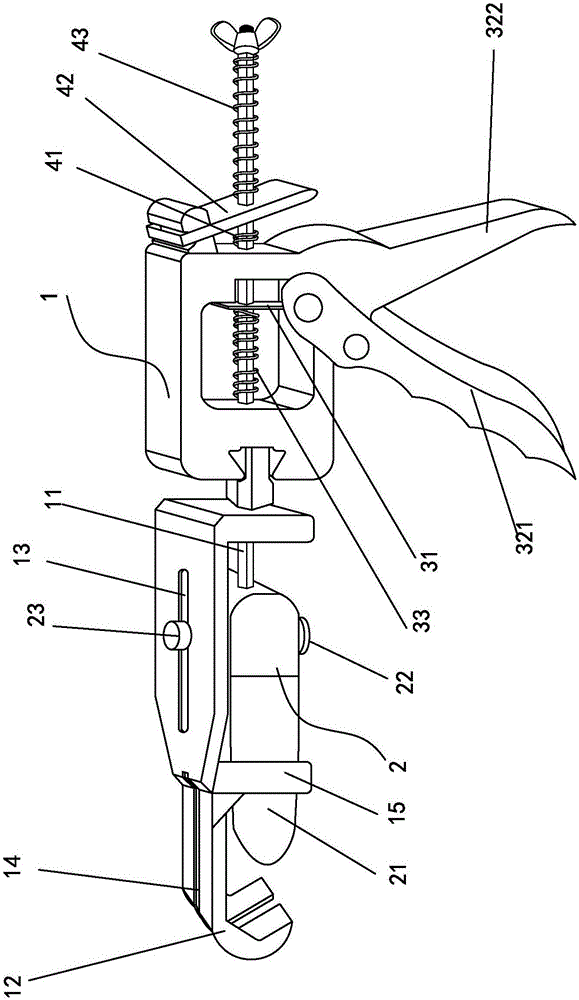
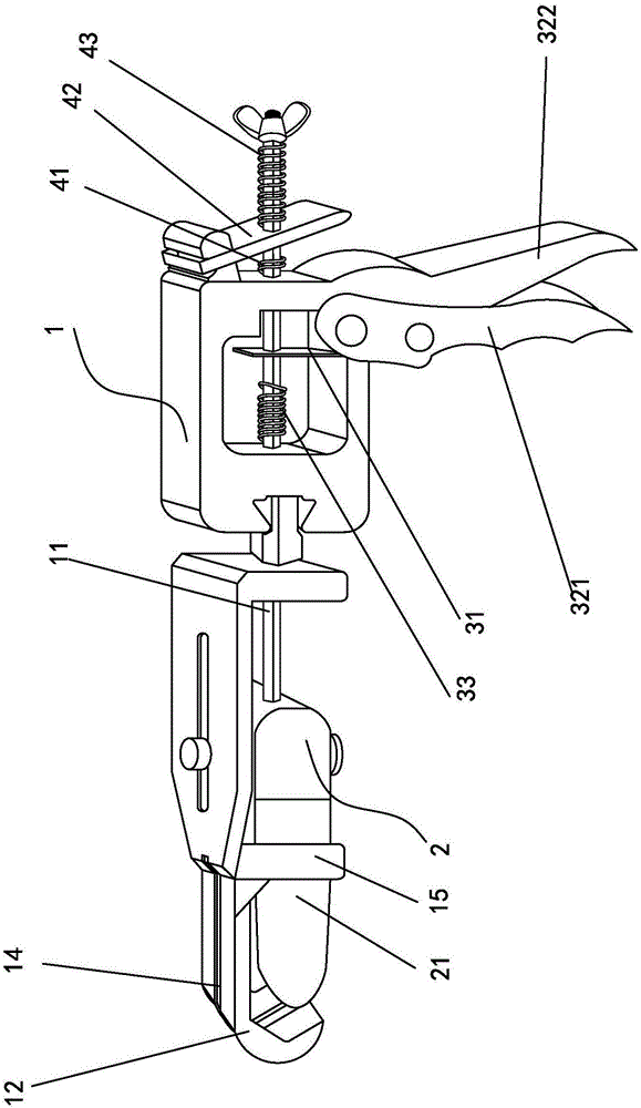
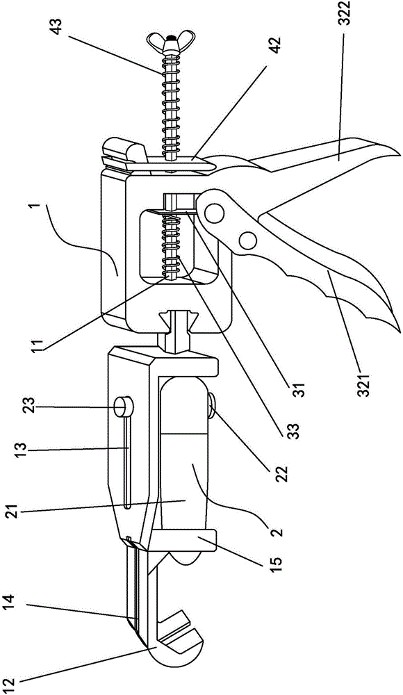
[0028] Embodiment one, see Figure 1 to Figure 3 As shown, a pipe cutting machine of the present invention includes a main body 1, a cutter 2 and a transmission mechanism, the main body 1 is provided with a driving rod 11, the cutter 2 is arranged at the front end of the driving rod 11, and the main body 1 The front end 12 is set as a hook-shaped structure, and the transmission mechanism is connected to the drive rod 11 to drive the drive rod 11 to advance so that the cutter 2 is pressed and cut towards the front end 12 of the hook-shaped structure in the main body 1 to cut the object to be cut; The transmission mechanism includes a transmission piece 31 and an operating handle that is transmission connected to the transmission piece 31 , and the transmission piece 31 is sleeved on the driving rod 11 to drive the driving rod 11 to move.

[0029] The blade 21 of the cutter 2 is an arc-shaped structure protruding outward. In order to improve the cutting force, the apex of the b...

Embodiment 2

[0036] Embodiment two, see Figure 4 As shown, the difference between this embodiment and Embodiment 1 is that the cutter 2' is movably arranged at the front end of the drive rod 11, wherein one end of the cutter 2' is pivotally connected to the main body 1, and the other One end is provided with a chute 24, and the front end of the drive rod 11 is slidably arranged in the chute 24; when the transmission mechanism drives the drive rod 11 forward, the cutter 2 rotates and squeezes the object to be cut .

[0037] The front end of the main body 1 is set as a plane, so that it can easily lean against a certain position.


PUM


Abstract

The invention discloses a pipe cutting machine. The pipe cutting machine comprises a main body, a cutter and a transmission mechanism; the main body is internally provided with a driving rod; the cutter is arranged at the front end of the driving rod, and the front end of the main body is of a hook-like structure; the transmission mechanism is in transmission connection with the driving rod to drive the driving rod to go forward, so that the cutter extrudes and cuts an object to be cut toward the front end of the hook-like structure in the main body; the transmission mechanism comprises a transmission piece and an operation handle which is in transmission connection with the transmission piece; and the driving rod is sleeved with the transmission piece to drive the driving rod to move. According to the pipe cutting machine, the hook-like front end and the cutter are matched to extrude and cut, compared with the different structure characteristics of an existing pipe cutting machine or a pipe cutting clamp, the pipe cutting machine has the characteristics that sliding is not easy to occur, operation is simple, efficiency is doubled, and repeated operation and using by a single hand can be realized.

Description

technical field [0001] The invention relates to a cutting machine, in particular to a pipe cutting machine which is easy to operate and labor-saving. Background technique [0002] The traditional pipe cutting machine first needs to be opened with both hands, and then the two handles are tightly closed to be used, and the operation is like scissors that are opened in two directions outwards and then closed in two directions inwards. This pipe cutting method needs to occupy a certain space to proceed smoothly. If the pipe is in a narrow space box, the traditional pipe cutting machine cannot be used. Contents of the invention [0003] The purpose of the present invention is to overcome the deficiencies of the prior art and provide a pipe cutting machine. [0004] The technical solution adopted by the present invention to solve its technical problems is: [0005] A pipe cutting machine, which includes a main body, a cutter and a transmission mechanism. A driving rod is arra...

Claims


Application Information

Patent Timeline
Patent Type & Authority Applications(China)
IPC IPC(8): B23D21/10
CPCB23D21/10
Inventor 张坤东
Owner 漳州荣鑫五金机械有限公司
Why Eureka
Try Eureka