Shift fork module

A technology of shift fork shaft and transmission module, which is applied in the direction of mechanical control devices, components with teeth, instruments, etc., can solve the problems of low operability, achieve smooth and accurate operation, simplify shifting operation and selection mode, and improve The effect of assembly precision

Active Publication Date: 2017-12-01
ATSUMITEC CO LTD
View PDF8 Cites 0 Cited by
  • Summary
  • Abstract
  • Description
  • Claims
  • Application Information

AI Technical Summary

Problems solved by technology

[0005] Therefore, in the prior art, in order to complete the power transmission and assemble the shift fork module on the transmission module, the operator must simultaneously perform two-stage assembly operations on one end of the reverse rod and the other end, and connect one end of the reverse rod to the On the operating member of the shift fork module, at the same time, the other end of the reverse lever is engaged with the reverse idler gear of the transmission module, which reduces the operability of the assembly

Method used


Image

  • Shift fork module
  • Shift fork module
  • Shift fork module

Examples


Embodiment Construction

[0052] In order to make the above-mentioned features and advantages of the present invention more comprehensible, the following specific embodiments are described in detail in conjunction with the accompanying drawings.

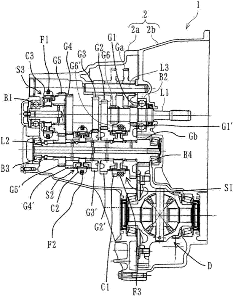
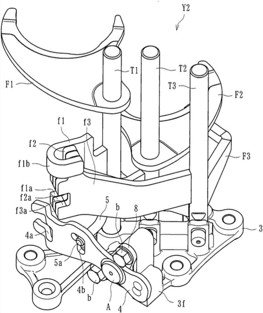
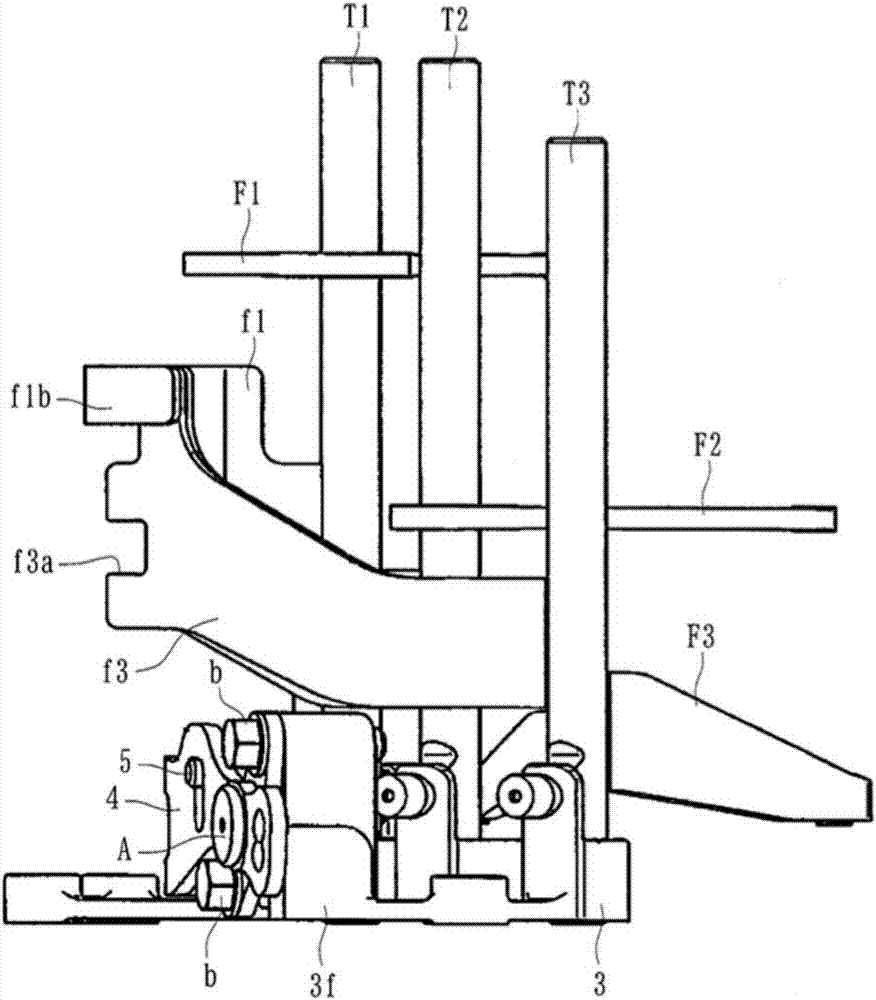
[0053] The power transmission 1 applied in the present embodiment (first and second embodiments) is installed on a vehicle such as an automobile, and obtains an arbitrary shift phase or reverse phase through the driver's operation. Such as Figure 1~4 As shown, the power transmission 1 is based on the fork module Y2 ( figure 2 ) assembled to the transmission module Y1 ( figure 1 ), wherein the input shaft L1 (first shaft), the main shaft L2 (second shaft), and the secondary shaft L3 (third shaft) of the transmission module Y1 are rotatably supported on the housing member 2b, and a plurality of dials The fork shafts T1 - T3 are slidably supported on the bottom member 3 . The power transmission 1 obtained by assembling the fork module Y2 and the transmissio...


PUM


Abstract

Provided is a shift fork module with which a reverse lever can be easily assembled, and with which ease of assembly in a gear module can be further improved. The shift fork module has: a plurality of shift fork shafts (T1 to T3) to which shift forks (F1 to F3) are attached; an actuating member (5) actuated when a transmission is shifted to reverse; a reverse lever (4) assembled by being coupled with the actuating member (5), one end of the reverse lever being engaged with a reverse idler gear when the reverse lever is assembled in a gear module (Y1), and the reverse lever being able through the actuation of the actuating member (5) to switch the reverse idler gear (Ga) between meshing and not meshing with a reverse drive gear and a reverse driven gear; and a base member (3) slidably supporting the shift fork shafts.

Description

technical field [0001] The invention relates to a shift fork module assembled on a transmission module to complete power transmission. Background technique [0002] Taking Patent Document 1: JP 2006-234010 as an example, the power transmission in the prior art includes a transmission case; the input shaft, output shaft and counter shaft supported by the transmission case ); transmission power from the input shaft to the output shaft through the layshaft to the gear train (gear train) of one to six speeds; multiple synchronizing mechanisms (synchronizing mechanisms) for switching the gear train to one to six speeds; engaged in A plurality of shift forks on corresponding sleeves of the synchronizing mechanism; a plurality of fork rods supporting the corresponding plurality of shift forks; and a housing closing an opening formed in the gearbox. [0003] According to the power transmission of the prior art, the input shaft, the output shaft, and the auxiliary shaft of the gear ...

Claims


Application Information

Patent Timeline
Patent Type & Authority Applications(China)
IPC IPC(8): F16H63/32
CPCF16H63/32F16H63/302F16H63/3069F16H2063/3079
Inventor 松田健司细田和史羽田雅敏高井浩文
Owner ATSUMITEC CO LTD
Why Eureka
Try Eureka