Power gearshift gearbox transmission device

A technology of gearbox transmission and power shifting, which is applied to multi-gear ratio transmissions, transmissions, gear transmissions, etc., can solve the problems of manual shifting, interruption of power output, and inability to bring power.

Pending Publication Date: 2017-12-01
SHANDONG WEIFANG LUZHONG TRACTOR
View PDF0 Cites 0 Cited by
  • Summary
  • Abstract
  • Description
  • Claims
  • Application Information

AI Technical Summary

Problems solved by technology

For large and heavy-duty tractors, the sliding resistance of the gearbox gears is relatively large, and manual shifting is very difficult; in addition, when the gearbox shifts gears, the cooperation of the clutch is required to change the meshing state of the gears. The existing tractors mainly use conventional gears, The mechanical reversing of the synchronizer or the meshing sleeve adopts flower-type shifting. In order to match the optimal working condition of the tractor, more gears are required, so the gearbox has at least one main transmission and multiple auxiliary transmissions
This requires a combination of multiple operating handles to achieve shifting. The driver needs to frequently operate each shifting handle, which is labor-intensive and prone to operational errors such as shifting gears.
In addition, most mechanically shifted gearboxes need to use the clutch to cut off the power output to change the meshing state of the gears. During the shifting process, the power output is interrupted, and the power cannot be shifted.

Method used


Image

  • Power gearshift gearbox transmission device
  • Power gearshift gearbox transmission device
  • Power gearshift gearbox transmission device

Examples


Embodiment Construction

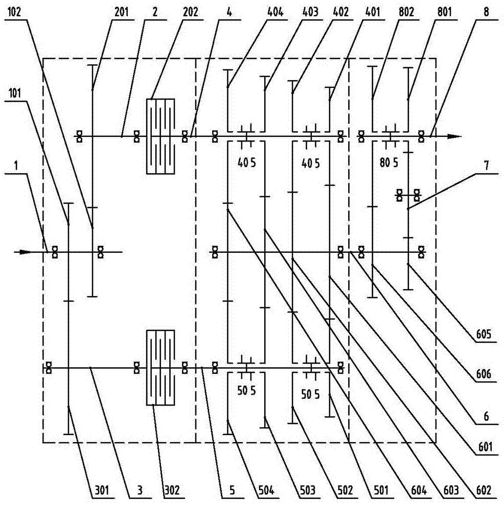
[0015] like figure 1 As shown, a transmission device of a power shift transmission according to the present invention includes a housing, an input mechanism installed in the housing, a shift mechanism and an output mechanism, wherein:

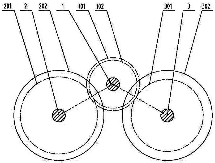
[0016] The input mechanism includes an input shaft 1, a left clutch shaft 2 and a right clutch shaft 3 arranged parallel to each other, a first input gear 101 and a second input gear 102 are fixedly installed on the input shaft 1, and a Left clutch gear 201, described left clutch gear 201 is constantly meshed with second input gear 102; On the right clutch shaft 3, right clutch gear 301 is fixedly installed, and described right clutch gear 301 is constantly meshed with first input gear 101; Like this, The power of the engine can be transmitted to the left clutch shaft 2 and the right clutch shaft 3 through the input shaft 1 simultaneously. The positional relationship of input shaft 1, left clutch shaft 2, and right clutch shaft 3 is as follows...


PUM


Abstract

The invention relates to the technical field of manufacturing of tractors, in particular to a power gearshift gearbox transmission device. The power gearshift gearbox transmission device comprises a shell, an input mechanism, a gearshift mechanism and an output mechanism, wherein the input mechanism, the gearshift mechanism and the output mechanism are installed in the shell. The gearshift mechanism comprises a left transmission shaft, a right transmission shaft and a power gearshift section output shaft, wherein the left transmission shaft, the right transmission shaft and the power gearshift section output shaft are mutually parallel. The output mechanism comprises a gearbox output shaft, a forward gear driven gear, a back gear driven gear and an output synchronizer, wherein the forward gear driven gear and the back gear driven gear are arranged on the gearbox output shaft in a sleeving manner. According to the power gearshift gearbox transmission device, hydraulic and mechanical execution mechanisms are controlled by a program to complete gear shifting, the power gearshift gearbox transmission device replaces manual action to push a shifting fork rod to move, the gear shifting operation is convenient, multiple kinds of gear change are provided, and manual misoperation can be effectively avoided.

Description

technical field [0001] The invention relates to the technical field of tractor manufacturing, in particular to a transmission device of a power shift gearbox. Background technique [0002] At present, the shifting device of the tractor all adopts the manual shift mechanism that the shift lever directly controls the shift fork to realize the gear meshing. For large and heavy-duty tractors, the sliding resistance of the gearbox gears is relatively large, and manual shifting is very difficult; in addition, when the gearbox shifts gears, the cooperation of the clutch is required to change the meshing state of the gears. The existing tractors mainly use conventional gears, The mechanical reversing of the synchronizer or the meshing sleeve adopts flower shifting. In order to match the optimal working condition of the tractor, more gears are required, so the gearbox has at least one main transmission and multiple auxiliary transmissions. This requires a combination of multiple ope...

Claims


Application Information

Patent Timeline
IPC IPC(8): F16H3/093F16H57/023F16H61/18F16H61/28
CPCF16H3/093F16H57/023F16H61/18F16H61/28F16H2200/006
Inventor 韩晓荣胥宏伟刘风平徐辉黄冬梅张延功
Owner SHANDONG WEIFANG LUZHONG TRACTOR
Why Eureka
Try Eureka