
Motion compensation detection device for robot terminal

A motion compensation and detection device technology, applied in measurement devices, instruments, manipulators, etc., can solve the problems of lack of error repair and compensation ability, low efficiency, execution errors, etc., to improve flexibility and accuracy, flexible and convenient use, and detection. high precision effect

Inactive Publication Date: 2017-12-01
NANJING YUSHENG ROBOT CO LTD
View PDF0 Cites 0 Cited by
  • Summary
  • Abstract
  • Description
  • Claims
  • Application Information

AI Technical Summary

Problems solved by technology

[0002] With the use of robotic equipment in daily life and work, robots have been used more and more in the fields of logistics warehousing, business services, and industrial production. However, during the operation of robotic equipment, it was found that due to the assembly process, equipment Running energy consumption and other reasons, as well as the existence of certain execution errors in the operation of the end-effector of the robot, have seriously affected the stability and reliability of the operation of the robot equipment, especially in some high-precision processing industries, these deviations have a great impact on the equipment and The processing quality of the workpiece has a great impact, and to solve this problem, the current method is mainly to carry out the positioning accuracy and error detection experiment before the operation of the robot equipment, and then perform error compensation on the robot operation program before the robot equipment can work. Although it can meet the needs of improving the robot's operating accuracy to a certain extent, the accuracy adjustment and error detection work is cumbersome and inefficient. During the operation of the robot, it is impossible to accurately compensate the low position of the robot's end actuator according to the error change in a timely and effective manner. Therefore, in view of this phenomenon, it is urgent to develop a robot operation obstacle avoidance device to meet the needs of actual use.

Method used

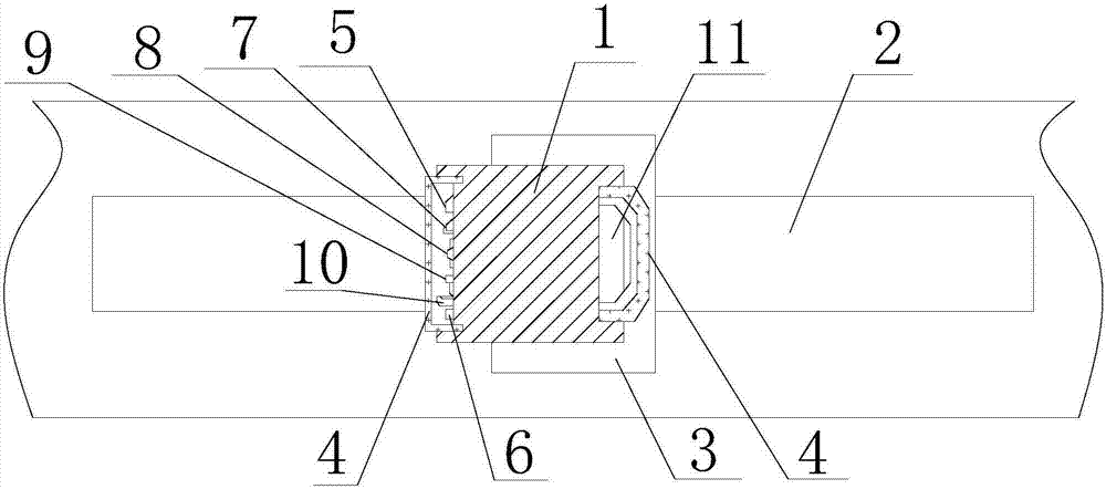

Image

  • Motion compensation detection device for robot terminal

Examples


Embodiment Construction

[0015] In order to make the technical means, creative features, goals and effects achieved by the present invention easy to understand, the present invention will be further described below in conjunction with specific embodiments.

[0016] like figure 1 The robot terminal motion compensation detection device includes a bearing base 1, a guide rail 2, a slider 3, a transparent protective cover 4, a displacement sensor 5, a pressure sensor 6, a distance measuring device 7, a height measuring device 8, The width measuring device 9, the 3D camera 10 and the data processing circuit 11, the guide rail 2 are installed on the outer surface of the robot terminal equipment 12 and distributed parallel to the axis of the robot terminal equipment 12, and the bearing base 1 passes through the slider 3 and the guide rail 2 Sliding connection, each guide rail 2 is equipped with a bearing base 1, displacement sensor 5, pressure sensor 6, distance measuring device 7, height measuring device 8,...


PUM


Abstract

The invention relates to a robot terminal motion compensation detection device, which includes a bearing base, a guide rail, a slider, a transparent protective cover, a displacement sensor, a pressure sensor, a distance measuring device, a height measuring device, a width measuring device, a 3D camera and data The processing circuit, the guide slide rail is installed on the outer surface of the robot terminal equipment, and the bearing base is slidably connected with the guide slide rail through the slider, and the displacement sensor, pressure sensor, distance measuring device, height measuring device, width measuring device, and 3D camera are all located on the The front end of the bearing base, the data processing circuit is installed on the rear end of the bearing base, and the transparent protective cover is connected to the bearing base. The present invention can effectively and accurately detect the stroke and offset of the robot terminal equipment, thereby timely and effectively discovering the offset in the operation of the robot, and repairing the offset in time, so as to improve the operation of the robot. and the purpose of controlling flexibility and accuracy.

Description

technical field [0001] The invention relates to a robot control device, in particular to a robot terminal motion compensation detection device. Background technique [0002] With the use of robotic equipment in daily life and work, robots have been used more and more in the fields of logistics warehousing, business services, and industrial production. However, during the operation of robotic equipment, it was found that due to the assembly process, equipment Running energy consumption and other reasons, as well as the existence of certain execution errors in the operation of the end-effector of the robot, have seriously affected the stability and reliability of the operation of the robot equipment, especially in some high-precision processing industries, these deviations have a great impact on the equipment and The processing quality of the workpiece has a great impact, and to solve this problem, the current method is mainly to carry out the positioning accuracy and error de...

Claims


Application Information

Patent Timeline
Patent Type & Authority Applications(China)
IPC IPC(8): B25J19/00G01D21/02
CPCB25J19/0095G01D21/02
Inventor 邵根顺
Owner NANJING YUSHENG ROBOT CO LTD
Learn More