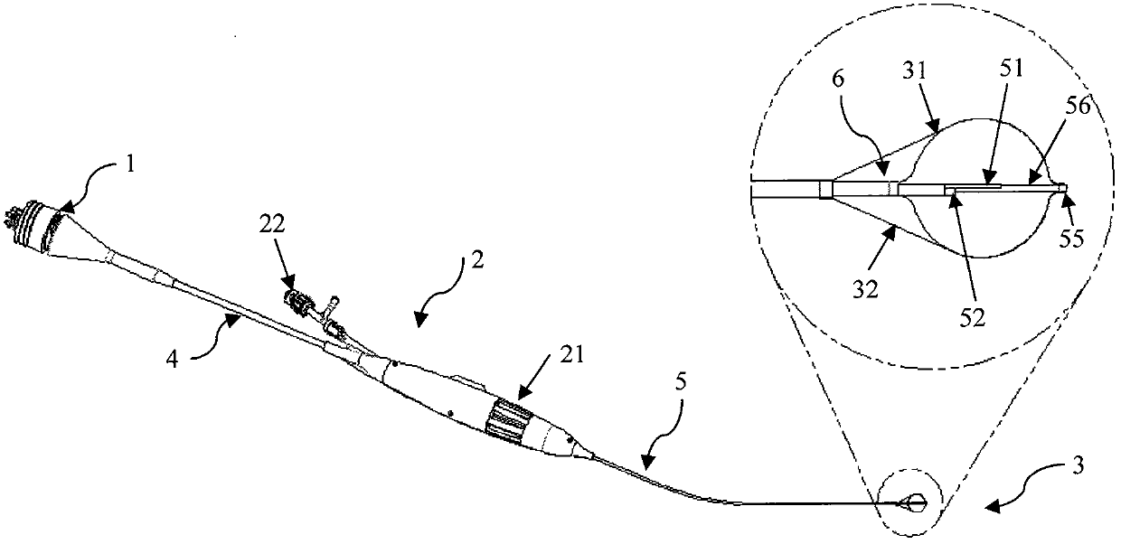
A cryoablation catheter and system
A technology for ablation of catheters and cold sources, applied in catheters, cooling surgical instruments, medical science, etc., can solve the problems of damaged surrounding tissues, high cost, complex structure, etc., to reduce damage, prevent heat transfer, and accelerate rewarming Effect
- Summary
- Abstract
- Description
- Claims
- Application Information
AI Technical Summary
Problems solved by technology
Method used
Image
Examples
Embodiment 1
[0070] Such as figure 1 As shown, a cryoablation catheter of the present invention includes: a cold source connector 1, a control handle 2, a freezing unit 3, a flexible connecting tube 4 and a tube body 5, and the tube body 5 having a distal end and a proximal end includes Extended cold source air intake cavity 51 and cold source return air cavity 52; the refrigeration unit 3 is arranged on the distal part of the pipe body 5, including The cavity 52 is in fluid communication with the first balloon body 31 and the second balloon body 32 disposed outside the first balloon body 31 , and the second balloon body 32 expands with the first balloon body 31 . The length of the first capsule 31 is smaller than that of the second capsule 32 . A part of the wall of the first capsule body 31 and the second capsule body 32 is in a bonded state, and the bonded part of the wall of the first capsule body 31 and the second capsule body 32 is frozen energy For the passage to the treatment sit...
Embodiment 2
[0078] The difference between this embodiment and Embodiment 1 is that a support structure is provided between the first balloon 31 and the second balloon 32 adjacent to the non-treatment area. When the first balloon 31 And when the second capsule 32 expands, the support structure can support the cavity 6 for isolating energy transmission formed between the first capsule 31 and the second capsule 32, thereby ensuring energy isolation The shape of the transmitted cavity 6 is stable and reliable.
[0079] In one embodiment, the support structure 33 is a balloon 331 disposed at the proximal end of the first balloon body 31 . Such as figure 2 As shown, the tubular body 5 also includes a balloon filling cavity 54 extending axially therethrough, and the balloon filling cavity 54 is in fluid communication with the balloon 331 . During the treatment, a proper amount of refrigerant is first injected into the first capsule 31 to expand the first capsule 31 and the second capsule 32 ....
Embodiment 3
[0081] The difference between this embodiment and Embodiment 2 is that: image 3 As shown, the support structure 33 can be made of one or more memory alloy wires 332 with a preset shape, and the support structure 33, the first balloon body 31 and the second balloon body 32 are in a compressed state before reaching the lesion site . When the first balloon 31 is delivered to the lesion, the supporting structure 33 can return to a preset shape, thereby supporting. Then the cryoablation treatment is started, and the refrigerant is injected into the first capsule 31 to absorb heat in the treatment area to achieve the effect of cryoablation. The memory alloy wire is preferably nickel-titanium wire. In a preferred embodiment, the preset shape includes a spiral shape (such as Figure 12a shown), cage (such as image 3 shown) or umbrella (such as Figure 16 shown). The memory alloy wire is shaped into a spiral shape, a cage shape or an umbrella shape through heat treatment.
PUM
 Abstract
Description
Claims
Application Information
 - Generate Ideas
- Intellectual Property
- Life Sciences
- Materials
- Tech Scout
- Unparalleled Data Quality
- Higher Quality Content
- 60% Fewer Hallucinations
Browse by: Latest US Patents, China's latest patents, Technical Efficacy Thesaurus, Application Domain, Technology Topic, Popular Technical Reports.
© 2025 PatSnap. All rights reserved.Legal|Privacy policy|Modern Slavery Act Transparency Statement|Sitemap|About US| Contact US: help@patsnap.com


