Winding device and winding method for bee pollen trap
A technology of powder remover and coil winding is applied in the field of coil winding device, which can solve the problems of wasting manpower and low efficiency of manual coil winding.
- Summary
- Abstract
- Description
- Claims
- Application Information
AI Technical Summary
Problems solved by technology
Method used
Image

Examples
Embodiment 1
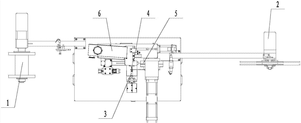
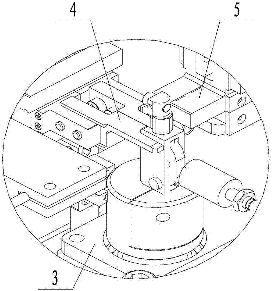
[0050] Such as Figure 1 to Figure 5 ,as well as Figure 8 The shown coiling device used in the honeybee powder remover includes a wire-releasing mechanism 1, a wire-receiving mechanism 2, a coiling mechanism 3, and a line clamp 4; the coiling mechanism 3 is located between the wire-releasing mechanism 1 and the Between the take-up mechanism 2, the winding mechanism 3 includes a first slide rail 31, a first slide block 32 capable of sliding on the first slide rail 31, and a first straight line for driving the first slide block 32. The drive device 33; the first slider 32 is provided with a second slide rail 34, a connecting portion 35 capable of sliding on the second slide rail 34, and a second linear drive device 36 for driving the connecting portion 35; the The output end of the second linear drive device 36 faces upwards and is connected with the connecting portion 35; it also includes a rotating shaft 37 fixed on the connecting portion 35, and the rotating shaft 37 is dri...
Embodiment 2
[0052] Such as Figure 1 to Figure 9 The shown coiling device used in the honeybee powder remover, on the basis of Embodiment 1, also includes a pull wire clamp 5 located in the direction of the parallel wire clamp 4 towards the wire take-up mechanism 2, and the pull wire clamp 5 It includes a second driving mechanism 13, a second mounting block 51 and a clamping mechanism that is slidably arranged on the second mounting block 51. The clamping mechanism includes two clamping blocks 52, and the clamping blocks 52 are both slidably disposed on On the side wall of the second mounting block 51 , the second driving mechanism 13 is connected to the clamping block 52 for driving the two clamping blocks 52 to contact or move away from each other. Several opposite through slots 53 are provided on the opposite surfaces of the clamping blocks 52 , and the axes of the through slots 53 are all perpendicular to the moving track of the clamping blocks 52 . On the mutual contact surfaces of ...
Embodiment 3
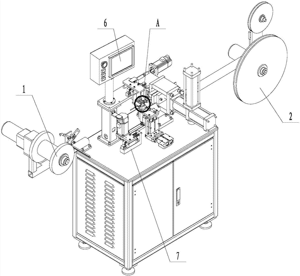
[0054] Such as Figure 1 to Figure 9Shown is a coiling device used in a honeybee depowder remover, on the basis of any of the above-mentioned embodiments, the power device is a motor, and the output end of the motor and the rotating shaft 37 are driven by a belt . Also includes a base 7, the base 7 is provided with a third slide rail 8, the third slide rail 8 is provided with a second slide block 9, the second slide block 9 can slide on the third slide rail 8; the base 7 is provided with a protruding portion 71 facing one end of the third slide rail 8; the second slider 9 is fixedly connected to the flat plate 10, and the motor is fixed on the flat plate 10; between the flat plate 10 and the protruding portion 71 The elastic member 11 is connected, and the axes of the third slide rail 8 and the elastic member 11 are parallel to the connecting line of the pay-off mechanism 1 and the take-up mechanism 2 .
PUM
 Abstract
Description
Claims
Application Information
 - R&D
- Intellectual Property
- Life Sciences
- Materials
- Tech Scout
- Unparalleled Data Quality
- Higher Quality Content
- 60% Fewer Hallucinations
Browse by: Latest US Patents, China's latest patents, Technical Efficacy Thesaurus, Application Domain, Technology Topic, Popular Technical Reports.
© 2025 PatSnap. All rights reserved.Legal|Privacy policy|Modern Slavery Act Transparency Statement|Sitemap|About US| Contact US: help@patsnap.com