High pressure gas container and high pressure gas container manufacturing method
A high-pressure gas, manufacturing method technology, applied in the direction of container discharge method, container filling method, pressure container, etc., can solve the problems of container durability reduction, heat difficult container body transfer, time-consuming, etc.
- Summary
- Abstract
- Description
- Claims
- Application Information
AI Technical Summary
Problems solved by technology
Method used
Image
Examples
no. 1 Embodiment approach
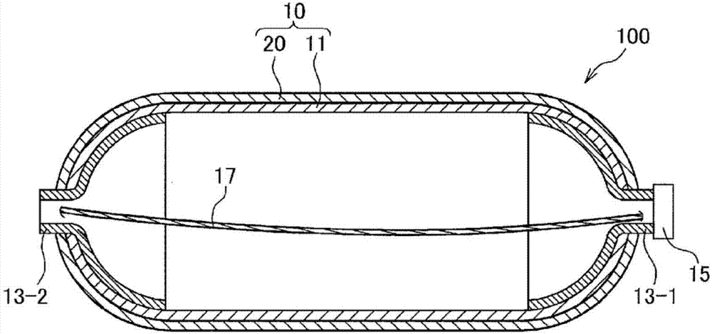
[0015] figure 1 It is a schematic configuration diagram illustrating the high-pressure gas container according to the first embodiment of the present invention.
[0016] The high-pressure gas container 100 of this embodiment includes: a substantially cylindrical container body 10; hubs 13-1, 13-2 disposed at both ends in the longitudinal direction of the container body 10; One hub 13 - 1 of the container main body 10 ; and a heat conductor 17 that connects the hub 13 - 1 on one side and the hub 13 - 2 on the other side inside the high-pressure gas container 100 .
[0017] Gas can be stored in a high-pressure state of 35Mpa or 70Mpa inside the high-pressure gas container 100 . Various gases are conceivable as the gas, and hydrogen gas is particularly conceivable in the present embodiment, and the high-pressure gas container 100 storing the hydrogen gas is mounted on, for example, a fuel cell vehicle.
[0018] In addition, the container main body 10 has: an inner layer body 11...
no. 2 Embodiment approach
[0042] Hereinafter, a second embodiment will be described. In addition, in each of the following embodiments, the same reference numerals are assigned to the same components as those in the preceding embodiments, and detailed descriptions will be omitted.
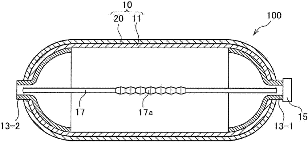
[0043] Figure 2A , Figure 2B It is a schematic configuration diagram of the high-pressure gas container 100 in the second embodiment of the present invention.
[0044] Figure 2A As shown, in the present embodiment, the hub portions 13 - 1 and 13 - 2 at both ends are connected by the heat conductor 17 configured as a rod-shaped metal shaft. In addition, a metallic corrugated portion 17 a serving as a displacement absorbing portion is formed at an approximately central portion in the axial direction of the heat conductor 17 . As a result, even when the container 100 undergoes deformation such as expansion, the displacement of the corrugated portion 17a is absorbed, so it is possible to suppress the concentration of loa...
no. 3 Embodiment approach
[0054] Hereinafter, a third embodiment will be described.
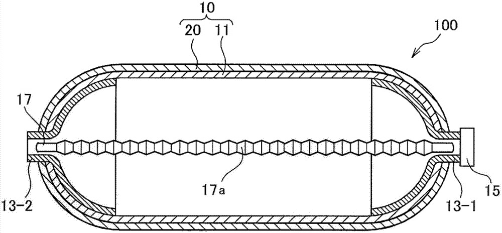
[0055] image 3 It is a schematic configuration diagram of the high-pressure gas container 100 in the third embodiment of the present invention. image 3 The high-pressure gas container 100 is provided with a filling flow path 30 for filling hydrogen gas at a hub portion 13-1 integrated with a plug valve 15 .
[0056] The filling flow path 30 is a flow path through which hydrogen gas supplied from an external filling device passes, and is opened and closed by an unillustrated main shut valve. In addition, in the present embodiment, the heat conductor 17 is arranged so as to intersect with the extension line C of the filling channel 30 inwardly of the inner layer body 11 . Specifically, as shown in the figure, one end 17b of the heat conductor 17 is fixed to the upper part of the inner peripheral surface of the hub 13-1 in the figure, and the other end 17c of the heat conductor 17 is fixed to the inner periphery of t...
PUM
 Abstract
Description
Claims
Application Information
 - R&D
- Intellectual Property
- Life Sciences
- Materials
- Tech Scout
- Unparalleled Data Quality
- Higher Quality Content
- 60% Fewer Hallucinations
Browse by: Latest US Patents, China's latest patents, Technical Efficacy Thesaurus, Application Domain, Technology Topic, Popular Technical Reports.
© 2025 PatSnap. All rights reserved.Legal|Privacy policy|Modern Slavery Act Transparency Statement|Sitemap|About US| Contact US: help@patsnap.com


