
Waste water aeration device used for water supply and drainage

An aeration device, water supply and drainage technology, applied in the direction of water aeration, water/sewage treatment, adsorption water/sewage treatment, etc., can solve the problem of insufficient contact with activated carbon, achieve the effect of speeding up the treatment of wastewater and improving work efficiency

Active Publication Date: 2017-11-28
亚太泵阀有限公司
View PDF3 Cites 8 Cited by
  • Summary
  • Abstract
  • Description
  • Claims
  • Application Information

AI Technical Summary

Problems solved by technology

[0006] In order to overcome the disadvantage that the oxygen in the air cannot be fully contacted with the activated carbon in the waste water in the present technology, the present invention is to provide a kind of waste water that can be fed intermittently, so that Wastewater aeration device for water supply and drainage fully combining activated carbon in wastewater with oxygen in the air

Method used


Image

  • Waste water aeration device used for water supply and drainage
  • Waste water aeration device used for water supply and drainage
  • Waste water aeration device used for water supply and drainage

Examples


Embodiment 1

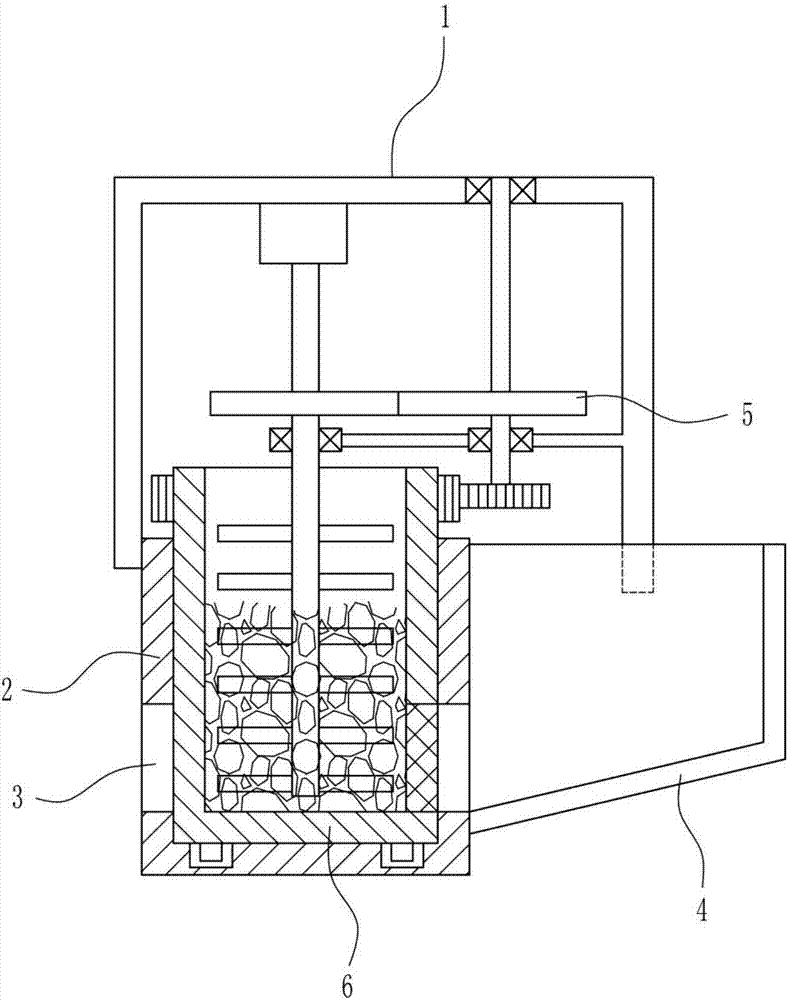
[0032] A wastewater aeration device for water supply and drainage, such as Figure 1-7 As shown, it includes a support 1, a treatment tank 2, a water storage tank 4, a drive mechanism 5 and an aeration mechanism 6. The left side of the bottom of the support 1 is connected with a treatment tank 2, and the right side of the bottom of the support 1 is connected with a water storage tank 4. The treatment tank The bottom of the left and right walls of 2 is provided with a through hole 3, the water storage tank 4 communicates with the through hole 3 on the left side of the treatment tank 2, the drive mechanism 5 is connected in the middle of the lower part of the support 1, and the treatment tank 2 is connected with an aeration mechanism 6. Pneumatic mechanism 6 is positioned at the bottom of driving mechanism 5.

Embodiment 2

[0034] A wastewater aeration device for water supply and drainage, such as Figure 1-7 As shown, it includes a support 1, a treatment tank 2, a water storage tank 4, a drive mechanism 5 and an aeration mechanism 6. The left side of the bottom of the support 1 is connected with a treatment tank 2, and the right side of the bottom of the support 1 is connected with a water storage tank 4. The treatment tank The bottom of the left and right walls of 2 is provided with a through hole 3, the water storage tank 4 communicates with the through hole 3 on the left side of the treatment tank 2, the drive mechanism 5 is connected in the middle of the lower part of the support 1, and the treatment tank 2 is connected with an aeration mechanism 6. Pneumatic mechanism 6 is positioned at the bottom of driving mechanism 5.

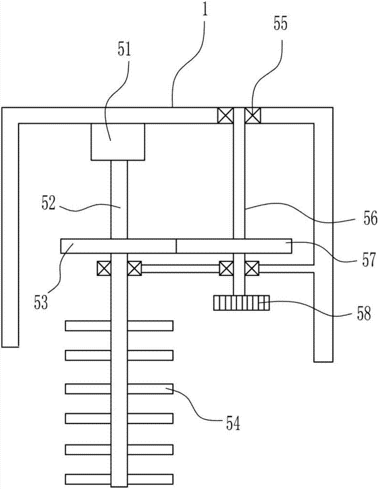
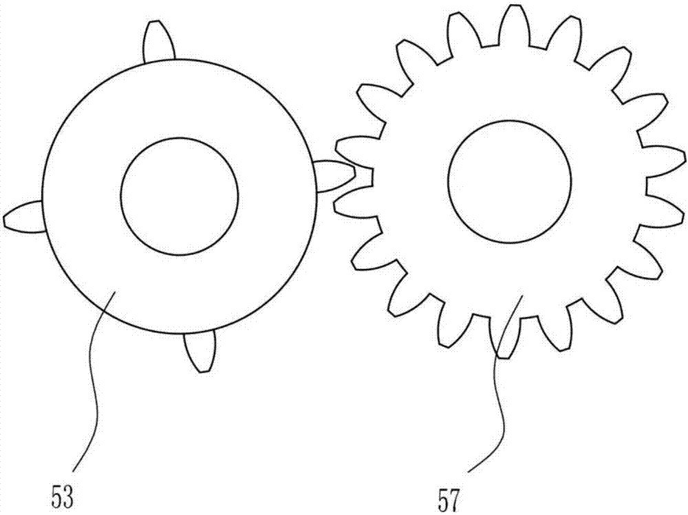
[0035] The driving mechanism 5 includes a motor 51, a first rotating rod 52, a missing gear 53, a stirring rod 54, a bearing seat 55, a second rotating rod 56, a first ge...

Embodiment 3

[0037] A wastewater aeration device for water supply and drainage, such as Figure 1-7 As shown, it includes a support 1, a treatment tank 2, a water storage tank 4, a drive mechanism 5 and an aeration mechanism 6. The left side of the bottom of the support 1 is connected with a treatment tank 2, and the right side of the bottom of the support 1 is connected with a water storage tank 4. The treatment tank The bottom of the left and right walls of 2 is provided with a through hole 3, the water storage tank 4 communicates with the through hole 3 on the left side of the treatment tank 2, the drive mechanism 5 is connected in the middle of the lower part of the support 1, and the treatment tank 2 is connected with an aeration mechanism 6. Pneumatic mechanism 6 is positioned at the bottom of driving mechanism 5.

[0038] The driving mechanism 5 includes a motor 51, a first rotating rod 52, a missing gear 53, a stirring rod 54, a bearing seat 55, a second rotating rod 56, a first ge...


PUM


Abstract

The invention relates to an aeration device, and especially relates to a waste water aeration device used for water supply and drainage. The waste water aeration device is capable of realizing intermittent waste water injection, and realizing complete combination of active carbon in waste water with oxygen in the air. The waste water aeration device comprises a support; the left side of the bottom of the support is connected with a treatment pool; the right side of the bottom of the support is connected with a water storage pond; the lower part of the left wall and the lower part of the right wall of the treatment pool are provided with through holes; the water storage pond is communicated with the through hole on the left side of the treatment pool; the middle part of the lower part of the support is connected with a driving mechanism; the treatment pool is connected with an aeration mechanism; and the aeration mechanism is arranged on the lower part of the driving mechanism. The waste water aeration device used for water supply and drainage is capable of realizing intermittent discharging and collecting of waste water, increasing the quality of processed waste water, reducing waste water impurity, and increasing impurity removing efficiency via arrangement of a cylinder body and a piston.

Description

technical field [0001] The invention relates to an aeration device, in particular to a wastewater aeration device for water supply and drainage. Background technique [0002] Water supply and drainage science and engineering is a kind of engineering discipline, referred to as water supply and drainage. Water supply and drainage science and engineering generally refer to urban water supply systems and drainage systems (municipal water supply and drainage and building water supply and drainage), referred to as water supply and drainage. [0003] The current wastewater treatment is to pass a large amount of wastewater into a treatment tank, and then use mechanical stirring to treat the wastewater. Too much wastewater is introduced at one time, which cannot be fully stirred, and the oxygen in the air cannot be fully contacted with the activated carbon in the wastewater. , leading to uneven treatment of wastewater, containing too many impurities. [0004] Therefore, there is an...

Claims


Application Information

Patent Timeline
IPC IPC(8): C02F9/08C02F7/00C02F1/28
CPCC02F1/001C02F1/283C02F7/00C02F9/00C02F2209/22C02F2303/14Y02W10/10
Inventor 方宣崇李婧王芳芳
Owner 亚太泵阀有限公司
Learn More