
An automatic unloading device

An automatic unloading and transmission shaft technology, applied in the field of logistics, can solve the problems of poor maneuverability, time-consuming and laborious logistics operations, and high price and cost, and achieve the effects of strong maneuverability, convenient transportation of goods, and improved performance.

Active Publication Date: 2019-02-05
重庆旭永科技发展有限公司
View PDF5 Cites 0 Cited by
  • Summary
  • Abstract
  • Description
  • Claims
  • Application Information

AI Technical Summary

Problems solved by technology

[0002] In logistics operations, we often encounter devices that transport goods from trucks or cranes from high places. Most of the current devices use goods to slide down from the springboard or carry bags off the springboard manually. Logistics operations are time-consuming and laborious. There is no device to flexibly adjust the inclination of the conveying plate and the unloading height to meet different conveying needs, poor maneuverability and low efficiency, and highly automated transportation equipment is difficult to be popularized due to its high cost

Method used


Image

  • An automatic unloading device

Examples


Embodiment Construction

[0011] The implementation of the present invention will be illustrated by specific specific examples below, and those skilled in the art can easily understand other advantages and effects of the present invention from the contents disclosed in this specification.

[0012] Below in conjunction with accompanying drawing and embodiment the present invention will be further described:

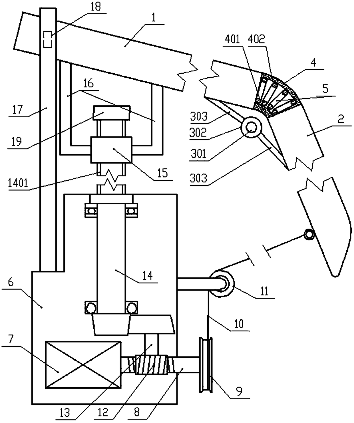
[0013] Such as figure 1 As shown, an automatic unloading device includes a conveying plate and a lifting mechanism; the conveying plate includes a first conveying plate 1 and a second conveying plate 2, wherein the bottom surface of the joint between the first conveying plate 1 and the second conveying plate 2 Hinged through damping hinges, and the two conveying plates are connected by a telescopic tube 4, the telescopic tube 4 is a hollow rectangular tube structure made of elastic rubber, and its fixed connection with the conveying plate depends on the material of the conveying plate, For example...


PUM


Abstract

The invention discloses an automatic demounting device which comprises conveying plates and a lifting mechanism. The conveying plates comprise the first conveying plate and the second conveying plate which are hinged to each other. The two conveying plates are connected through a telescopic pipe made of rubber, and a cylinder spring is arranged in the telescopic pipe. The lifting mechanism comprises a machine box, a motor is arranged in the machine box, a rolling wheel is arranged at the tail end of an output shaft of the motor, and after being wound around a pulley, a steel cable on the rolling wheel is connected with the second conveying plate. The part, located in the machine box, of the output shaft is of a worm structure and is in engagement transmission with a horizontally-arranged worm gear. A worm is fixed to a vertically-arranged first transmission shaft, and the first transmission shaft transmits torque to a second transmission shaft. The top end of the second transmission shaft stretches out of the top of the machine box, a thread is arranged on the stretching-out segment of the second transmission shaft, and a transmission nut is screwed on the threaded segment of the second transmission shaft and connected with the bottom face of the first conveying plate. A guide rail is further vertically arranged on the machine box. A guide wheel on the edge of one side of the first conveying plate is located in a sliding groove of the guide rail. The automatic demounting device is high in automation degree and quite high in maneuvering flexibility.

Description

technical field [0001] The invention belongs to the technical field of logistics, and in particular relates to cargo unloading equipment in logistics transportation. Background technique [0002] In logistics operations, we often encounter devices that transport goods from trucks or cranes from high places. Most of the current devices use goods to slide down from the springboard or carry bags off the springboard manually. Logistics operations are time-consuming and laborious. There is no device for flexibly adjusting the inclination of the conveying plate and the unloading height to meet different conveying needs, resulting in poor maneuverability and low efficiency, and highly automated transportation equipment is difficult to be popularized because of its high cost. Contents of the invention [0003] The purpose of the present invention is to provide an automatic unloading device, which has the advantages of maneuverability, high work efficiency and strong adaptability. ...

Claims


Application Information

Patent Timeline
Patent Type & Authority Patents(China)
IPC IPC(8): B65G67/24B65G11/00
CPCB65G11/00B65G67/24
Inventor 周宗金周明韩小涛
Owner 重庆旭永科技发展有限公司
Learn More