Eureka AIR delivers breakthrough ideas for toughest innovation challenges, trusted by R&D personnel around the world.

High-rise residential building cable laying control system and method

A cable laying and control system technology, applied in cable laying equipment and other directions, can solve problems such as low degree of automation, unbalanced cable tension, and easy scratching, etc., to achieve a high level of automation, easy operation, and ensure the effect of laying quality.

Pending Publication Date: 2017-11-24
TIANJIN 20 CONSTR
View PDF2 Cites 6 Cited by
  • Summary
  • Abstract
  • Description
  • Claims
  • Application Information

AI Technical Summary

Problems solved by technology

[0002] In modern industrial and civil construction cable laying construction, the cable tray bracket is often used to hold the cable, and the drag roller is set to hold the cable, and the cable is laid by manual pulling or by electric hoisting. The pulling force is uneven. When a single large long-distance cable is laid, this method is difficult and prone to scratches, twisting or other cable damage problems
[0003] At present, in addition to using manual, electric hoisting or setting damping retarders for high-rise residential buildings, but from the perspective of the automation level of existing methods and equipment, there are problems such as low automation and damage to cables. , cannot safely and quickly carry out the cable laying requirements of high-rise residential buildings

Method used

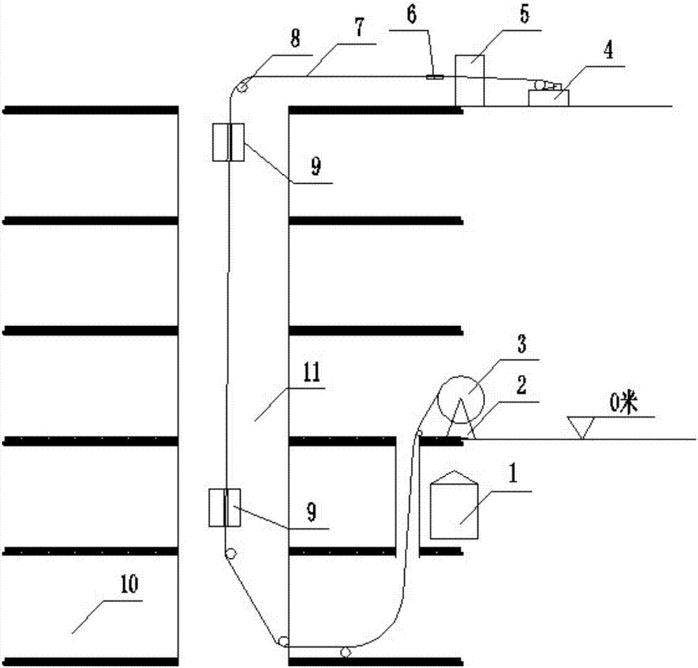
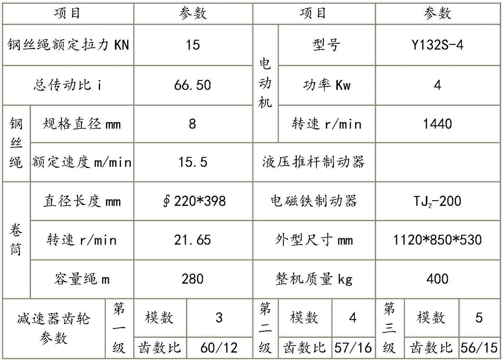

Image

  • High-rise residential building cable laying control system and method
  • High-rise residential building cable laying control system and method
  • High-rise residential building cable laying control system and method

Examples


Embodiment Construction

[0031] The present invention will be further described below in conjunction with the accompanying drawings and specific embodiments.

[0032] like figure 1 As shown, the present invention relates to a control system for laying cables in high-rise residential buildings, which is used for laying cables in high-rise residential buildings. The control system includes a control unit, a power unit and an auxiliary unit. The control unit is used to control the speed of the power unit. The power unit is used to run the cable 7 in the cable reel 3 from the ground through the strong electric well 11 from the basement 10 to the top floor of a high-rise residential building. When the cable 7 moves, it is used to provide power for the movement of the cable 7. The auxiliary unit is for the cable. 7 provides auxiliary power for the cable 7 during movement, and prevents the cable 7 from being in direct contact with the ground, so as to prevent the cable 7 from being scratched, so that the cab...


PUM


Abstract

The invention provides a high-rise residential building cable laying control system and a high-rise residential building cable laying control method. The high-rise residential building cable laying control system comprises a control unit, a power unit and an auxiliary unit. The control unit is electrically connected with the power unit. The power unit and the auxiliary unit are connected by means of a cable. The control unit comprises a frequency converter and a button box. The power unit comprises a hoisting machine and a brake. The frequency converter is electrically connected with the hoisting machine, the frequency converter is electrically connected with the button box, and the hoisting machine is electrically connected with the brake. The high-rise residential building cable laying control system and the high-rise residential building cable laying control method have the beneficial effects that: the frequency converter is connected with the hoisting machine, so that the whole high-rise residential building cable laying system is simple in structure and convenient in operation; the frequency conversion technology is combined with a high-rise residential building cable laying method, the unique frequency conversion technology is utilized, the frequency conversion technology is combined with a low-speed hoisting and traction cable laying method, the cable laying speed is accelerated, and the cable laying quality is guaranteed; and the automation level is high, the labor cost is saved and the working efficiency is improved.

Description

technical field [0001] The invention belongs to the technical field of cable laying in high-rise residential buildings, and relates to a control system and method for cable laying in high-rise residential buildings, in particular to a vertical cable laying method for high-rise residential buildings. Background technique [0002] In modern industrial and civil construction cable laying construction, the cable tray bracket is often used to hold the cable, and the drag roller is set to hold the cable, and the cable is laid by manual pulling force or by electric hoisting. The pulling force is not balanced. When a single large long-distance cable is laid, this method is difficult and prone to scratches, twisting or other cable damage problems. [0003] At present, in addition to using manual, electric hoisting or setting damping retarders for high-rise residential buildings, but from the perspective of the automation level of existing methods and equipment, there are problems suc...

Claims


Application Information

Patent Timeline
Patent Type & Authority Applications(China)
IPC IPC(8): H02G1/06
CPCH02G1/06
Inventor 武立志王士芳白金元丁文青张晓艳李兴旺李会力耿彩霞
Owner TIANJIN 20 CONSTR
Why Eureka
Eureka Blog
Learn More