
Wind power resistor with stable insulating property

A resistor and wind power technology, applied in the direction of resistors, resistor components, circuits, etc., can solve the problems of reduced electrical insulation performance, harsh environment for wind power resistors, and low temperature, and achieve the effect of ensuring insulation performance

Inactive Publication Date: 2017-11-24
GUANGDONG FULLDE ELECTRONICS +1
View PDF5 Cites 5 Cited by
  • Summary
  • Abstract
  • Description
  • Claims
  • Application Information

AI Technical Summary

Problems solved by technology

However, the operating environment of wind power resistors is relatively harsh—the humidity is high and the temperature is low, and the surface of the porcelain casing 7 is prone to condensation; and the conductive ring 6 is close to the porcelain casing 7, and the condensation will seep into the conductive ring 6. On the one hand, it will This leads to a reduction in the electrical insulation performance between the resistance sheet 2 and the outside world, and on the other hand, it will affect the electrical conductivity of the adjacent resistance sheet 2
The string rod 3 generally includes a screw rod and a mica layer covering the outside of the screw rod. The resistor sheet 2 is directly mounted on the string rod 3. During transportation or after long-term use, the mica layer between the resistor sheet 2 and the screw rod is easily damaged. damage, resulting in electrical conduction between the resistor sheet 2 and the screw, affecting the normal operation of the entire resistor

Method used


Image

  • Wind power resistor with stable insulating property
  • Wind power resistor with stable insulating property
  • Wind power resistor with stable insulating property

Examples


Embodiment Construction

[0025] The present invention will be described in detail below in conjunction with specific embodiments and accompanying drawings.

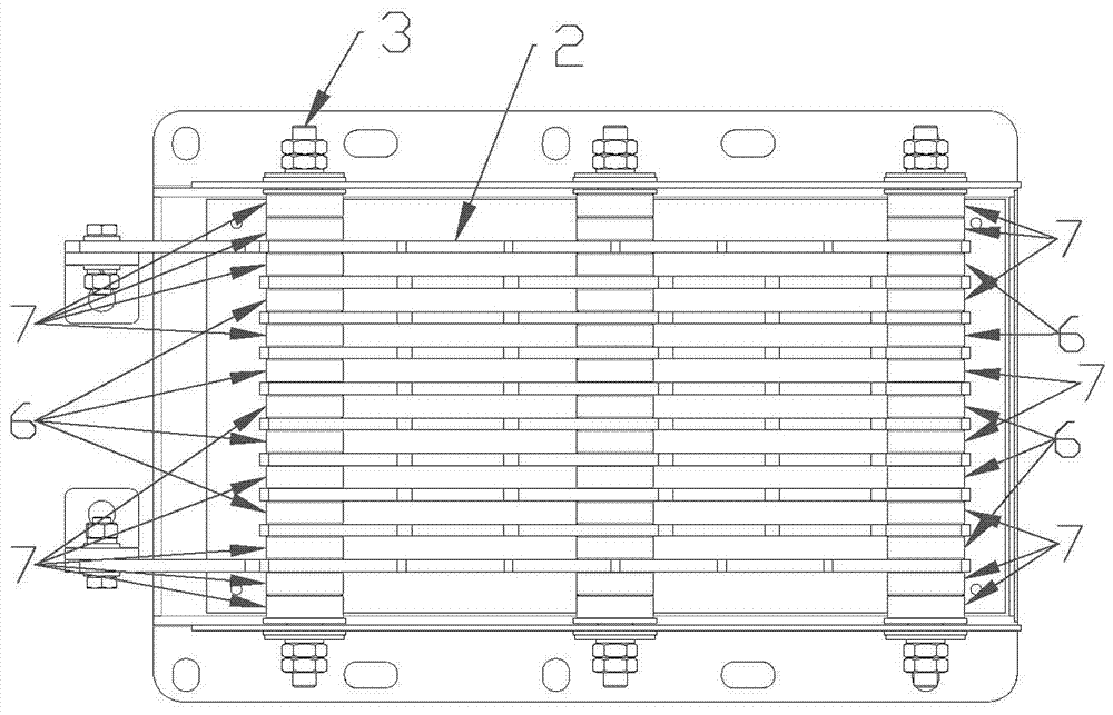
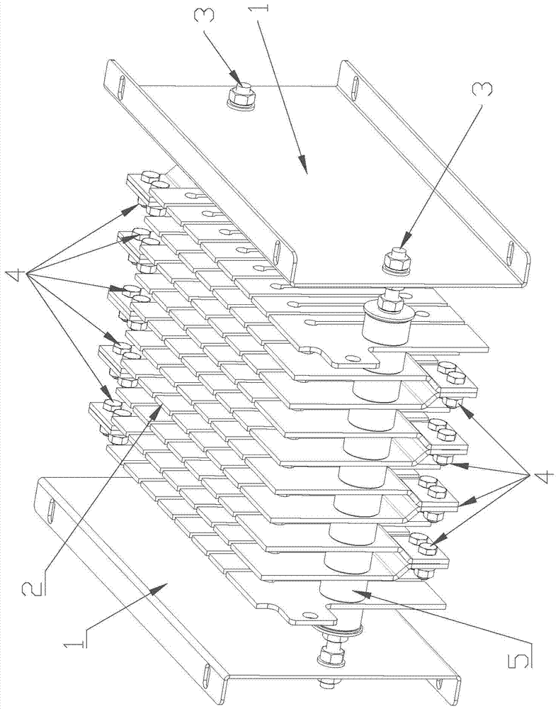
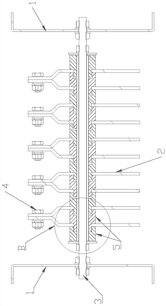
[0026] A wind power resistor with stable insulation in this embodiment, such as figure 2 with image 3 As shown, it includes two side plates 1, a plurality of parallel resistance sheets 2, and a string rod 3 connecting multiple resistance sheets 2 in series. superior. Such as Figure 4 As shown, the skewer 3 includes a screw 31 and a mica layer 32 coated on the outer surface of the screw 31 . The string rod 3 has a plurality of insulators 5 for electrical insulation between two adjacent resistance sheets 2, and the insulators 5 are porcelain sleeves or other insulating materials. The end of the resistor sheet 2 is connected with a conductive piece 4 for electrical conduction between multiple resistor sheets 2. The conductive piece 4 includes a matching conductive bolt and a conductive nut. The ends between two adjacent resistor sheets 2 Bot...


PUM


Abstract

The invention discloses a wind power resistor with a stable insulating property. The wind power resistor comprises a plurality of resistor discs arranged in parallel and stringing rods for stringing the plurality of resistor discs; conductive parts are connected to end parts of the resistor discs and are used for electrically conducting the plurality of resistor discs; a plurality of insulating parts are stringed on the stringing rods and are used for electrically insulating every two adjacent resistor discs; a flange is arranged on each insulating part in an extending manner; the resistor discs sleeve the corresponding flanges, so that the resistor discs are separated from the stringing rods by the flanges. Compared with the prior art, the wind power resistor has the advantages that an electric conducting part between every two adjacent resistor discs is arranged at the end parts of the resistor discs and is away from the insulating part easily forming condensation, so that the influence of the condensation on electrical conductivity between the adjacent resistor discs or the insulating property between the resistor discs and the outside can be avoided. In addition, the flanges are arranged on the insulating parts and are used for separating the resistor discs from the stringing rods, so that the insulating property between the resistor discs and the stringing rods can be sufficiently ensured.

Description

technical field [0001] The invention relates to the technical field of resistors, in particular to a wind power resistor with stable insulation. Background technique [0002] Wind power resistors are mainly used in the low voltage ride through technology of wind power inverters. It is used in the rotor of the wind turbine to bypass the rotor converter. When the grid has a low voltage disturbance, the wind power resistor can prevent the DC bus voltage from being too high and the rotor current from being too large. Wind resistors can dissipate huge energy in an instant. As a clean and renewable energy, wind energy has attracted more and more attention from all over the world. Wind power converters can optimize the operation of wind power generation systems, realize variable speed and constant frequency power generation within a wide wind speed range, and improve fan efficiency and transmission chain work. conditions, reduce generator loss, improve operating efficiency, and i...

Claims


Application Information

Patent Timeline
IPC IPC(8): H01C13/02H01C1/014
CPCH01C1/014H01C13/02
Inventor 莫焕堂周华俊王锦全黎志盈
Owner GUANGDONG FULLDE ELECTRONICS
Learn More