Air-source heat pump drying room

An air energy heat pump, drying room technology, applied in drying, dryer, drying gas layout and other directions, can solve the problems of poor reliability, large cost and volume, and reduced volume, and achieves a simple structure and convenient use. Effect

Pending Publication Date: 2017-11-24
山东三土能源股份有限公司
View PDF5 Cites 7 Cited by
  • Summary
  • Abstract
  • Description
  • Claims
  • Application Information

AI Technical Summary

Problems solved by technology

[0002] As we all know, drying and dehumidification is an indispensable process in many industrial productions, food productions, and agricultural and sideline products processing. For example, traditional fruit drying is made of masonry as a stove and a layered drying tower, and dry wood is burned for drying. Drying, when the amount of fruit material is large, it must be burned day and night for dozens of days to complete the entire drying process, which not only wastes forest resources, but also produces thick smoke and pollutes the environment
[0003] At present, the heat pump dryer uses the reverse Carnot principle to absorb the heat of the air and transfer it to the room to increase the temperature of the drying room, and cooperate with the corresponding equipment to realize the drying of materials. There are also air energy heat pumps for heating and dehumidification. Drying structure, but some units use two independent systems, which are equivalent to a heat pump + a dehumidification. The unit adopts a system, one condenser is equipped with two evaporators, and the valve is used to switch between heat pump or dehumidification mode, which reduces the cost and volume, but has higher requirements on system design and oil return control, and the reliability is not as good as the former. , so both have pros and cons

Method used


Image

  • Air-source heat pump drying room
  • Air-source heat pump drying room

Examples


Embodiment

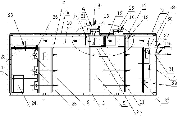
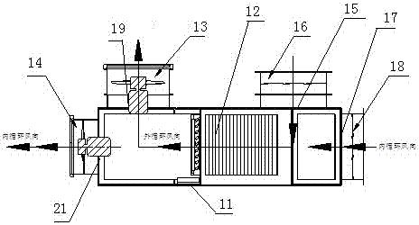
[0022] First, set the drying temperature to 65°C and the humidity to 10%. Put the material into the drying room, turn on the system switch, and make the condenser, evaporator, circulating fan, and soaking fan work. When the humidity passing through the humidity sensor is 85%, 80% higher than the set value of the humidity sensor, the humidity is obviously too high, the humidity sensor transmits the humidity signal to the controller, and the controller controls the fresh air valve to open the dehumidification fan, open for rapid dehumidification, when the humidity is lower than the temperature When the set value of the sensor is 80%, the controller will close the humidity exhaust fan and the fresh air valve, and then carry out the internal drying and dehumidification process. After the temperature sensor in the drying room senses that the temperature is lower than the set temperature The external circulation is used for heating. At this time, the evaporator fan and the first elec...


PUM


Abstract

The invention relates to the technical field of air-source heat pumps, in particular to an air-source heat pump drying room. The air-source heat pump drying room comprises a room body and is characterized in that the room body is internally provided with a drying chamber, an air passage circulation cavity is formed between the drying chamber and an inner cavity of the room body, and an air path switching unit is arranged in the air passage circulation cavity between an upper drying plate of the drying chamber and an upper plate of the room body. A fluorine system condenser in the drying room is separated from an evaporator, the condenser portion is a heating portion, and the evaporator portion is an air energy conversion and condensation and dehumidification portion. Air energy conversion and condensation and dehumidification functions are completed through air path switching by taking the advantage of intrinsic functions of the evaporator, and a current mode of adopting a double-evaporator or double-condenser mechanism for completing an internal and external dual-circulation dewatering process of the air-source heat pump drying room is changed. The drying room only adopts one normal fluorine system device to complete the internal and external dual-circulation dewatering process of the air-source heat pump drying room by air path switching, thereby having advantages of convenience in use, economical, energy efficient, completion of dehumidification and heating through air path switching, and the like.

Description

technical field [0001] The present invention relates to the technical field of air source heat pumps, and specifically relates to an air source heat pump drying room with simple structure, convenient use, economy and energy saving, and dehumidification and heating through switching of air channels. Background technique [0002] As we all know, drying and dehumidification is an indispensable process in many industrial productions, food productions, and agricultural and sideline products processing. For example, traditional fruit drying is made of masonry as a stove and a layered drying tower, and dry wood is burned for drying. Drying, when the amount of fruit material is large, it must be burned day and night for dozens of days to complete the entire drying process, which not only wastes forest resources, but also produces thick smoke and pollutes the environment. [0003] At present, the heat pump dryer uses the reverse Carnot principle to absorb the heat of the air and tran...

Claims


Application Information

Patent Timeline
IPC IPC(8): F26B9/02F26B21/04F26B21/08
CPCF26B9/02F26B21/002F26B21/04F26B21/086
Inventor 邹本尧安斌张靖雨滕新双王佳伟于德强孙浩然
Owner 山东三土能源股份有限公司
Why Eureka
Try Eureka