
Energy absorbing device of coupling-necking and spalling-deformation

An energy-absorbing device and necking technology, which is used in transportation and packaging, railway car body parts, railway vehicle wheel guards/buffers, etc., can solve problems such as deformation and instability, and achieve stable plastic deformation, stable impact force, The effect of enhancing the ability to absorb shock kinetic energy

Active Publication Date: 2017-11-24
CENT SOUTH UNIV
View PDF6 Cites 4 Cited by
  • Summary
  • Abstract
  • Description
  • Claims
  • Application Information

AI Technical Summary

Problems solved by technology

The other is the bulging / neck-type energy-absorbing structure. After the force-displacement curve increases sharply with the displacement, it will stabilize at about a platform force, which is much more stable than the impact force of the crushing-type energy-absorbing structure. , especially when the bulging / crushing tube is pre-deformed, but in the actual application process, there is a situation that the non-bulging / neck part is pre-collapsed, resulting in deformation instability

Method used


Image

  • Energy absorbing device of coupling-necking and spalling-deformation
  • Energy absorbing device of coupling-necking and spalling-deformation
  • Energy absorbing device of coupling-necking and spalling-deformation

Examples


Embodiment Construction

[0033] In order to facilitate the understanding of the present invention, the present invention will be described more fully and in detail below in conjunction with the accompanying drawings and preferred embodiments, but the protection scope of the present invention is not limited to the following specific embodiments.

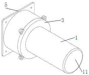
[0034] see Figure 1 to Figure 11 As shown, an embodiment of an energy-absorbing device coupling necking and expansion crack deformation of the present invention includes a mounting base 5, a guide rod 2, a bulging boss 4, a necking flange 3 and a necking deformation tube 1, and the guide rod 2. One end is inserted into the guide through hole 55 provided on the installation base 5, and the bulging boss 4 is sleeved on the guide rod 2 through the guide hole 45 provided in the middle and is located in the installation cavity of the installation base 5. The necking deformation tube 1 is sleeved on the guide rod 2, and the mouth of the small-diameter tube 13 is p...


PUM


Abstract

The invention discloses an energy absorbing device of coupling-necking and spalling-deformation. The energy absorbing device of coupling-necking and spalling-deformation comprises an installing base, a guiding rod, a ballooning convex platform, a necking flange and a necking deformation pipe. One end of the guiding rod is arranged in a guiding through hole of the installing base in an inserting mode. The ballooning convex platform is located in an installing cavity of the installing base and arranged on the guiding rod through a guiding hole of the ballooning convex platform in a sleeving mode. The necking deformation pipe is arranged on the guiding rod in the sleeving mode. A plurality of small grooves are formed in a pipe opening of a small diameter pipe of the necking deformation pipe, and the small diameter pipe is arranged at the periphery of the ballooning convex platform in the sleeving mode. A bottom plate is arranged at the end of a large diameter pipe, and the end of the large diameter pipe makes contact with the end part of the other end of the guiding rod to be used as an impacting end. The necking flange is arranged on the outer side of the necking deformation pipe in the sleeving mode and in a matched mode through a necking through hole of the necking flange and fixedly connected with the installing base. A storing cavity which can store coupling-necking and spalling-buckling-deformation caused by moving after the necking deformation pipe is impacted is formed between the periphery of the ballooning convex platform, the end part of the necking flange and the inner wall of the installing base. The energy absorbing device of coupling-necking and spalling-deformation has the advantages of being simple in structure, convenient to install, saving in cost, high in energy absorbing capability, stable and controllable in deformation and the like.

Description

technical field [0001] The invention relates to the technical field of rail vehicle passive safety, in particular to an energy-absorbing device coupled with necking and bursting deformation. Background technique [0002] As the main artery of the national economy and a popular means of transportation, rail transit has the characteristics of large capacity, high speed, low cost, relatively high safety, environmental protection and energy saving. Rail transit has developed rapidly in recent years, especially high-speed passenger trains ushered in a booming period. As the operating speed continues to increase, the safety of vehicles is becoming more and more important. The probability of vehicle collisions is relatively small, but once a collision occurs, it will bring huge casualties and property losses. [0003] In order to reduce the harm caused by vehicle collision accidents and carry out passive safety protection of vehicles, it is necessary to study the special energy-ab...

Claims


Application Information

Patent Timeline
IPC IPC(8): B61F19/04
CPCB61F19/04
Inventor 谢素超王宁高广军李海红王达冯哲骏
Owner CENT SOUTH UNIV
Learn More