
Flame wire printing machine structure

A line printing machine and flame technology, which is applied in the field of medical device product line printing machines, can solve the problems of uniform heating of barrels of cylindrical plastic instruments, etc., to achieve enhanced competitiveness, increased production efficiency, and easy operation Effect

Inactive Publication Date: 2017-11-24
YIHENG MEDICAL DEVICE TECH SHANGHAI CO LTD
View PDF10 Cites 0 Cited by
  • Summary
  • Abstract
  • Description
  • Claims
  • Application Information

AI Technical Summary

Problems solved by technology

In the existing patent No. 201320037028, it is indeed mentioned that the flame processor is added to the line printing machine, so as to achieve the effect of combining the two, but the idea is simply to directly add the flame processor to the main machine of the line printing machine To achieve the purpose of heating, the structure of the flame device has not been described in detail, and how to make the barrel of the cylindrical plastic instrument evenly heated has not been considered. A structure of heating, and can be applied to actual operation, to achieve a win-win result of enhancing printing quality and increasing work efficiency

Method used


Image

  • Flame wire printing machine structure
  • Flame wire printing machine structure

Examples


Embodiment Construction

[0017] In order to describe the structure and characteristics of the present invention in more detail, an embodiment is given below in conjunction with figure 1 figure 2 Describe the structure of a flame marking machine of the present invention.

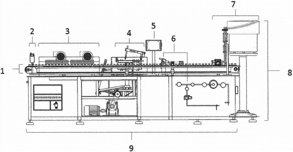
[0018] figure 1 The flame marking machine shown includes a conveyor chain system 1, a silicone oil injection system 2, a heating lamp drying system 3, a printing system 4, a digital control panel 5, a flame system 6, a feeding system 7, and a vibration feeder 8. The flame structure 6 is placed in the previous process of the printing system 4 .

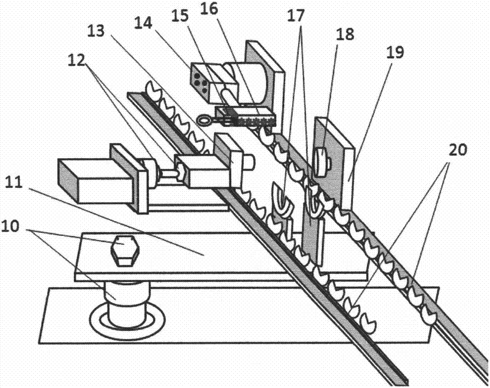
[0019] figure 2 In the schematic diagram of the flame structure of the line printing machine shown, debugging is carried out before printing, the drum is placed on 17, and the height of the drum supported by 17 is adjusted through 10, so that the highest lifting point of the drum can be matched with the thimble in 13. , 18 are in the same horizontal plane. Through 12 optimize the posit...


PUM


Abstract

The invention discloses a flame structure of a wire printing machine, and relates to the field of medical instrument product wire printing machines. The flame structure is creatively integrated into a local machine of the wire printing machine, and a method for merely embedding a flame treatment machine into the wire printing machine is abandoned. The flame structure comprises a set of rotor mechanism and a set of flame device. The rotor mechanism is composed of a rotor component, a thimble opposite to a rotor and a barrel lifting carrier, and the rotor component, the thimble and the barrel lifting carrier work in a preset program to enable a barrel body of a barrel to rotate. The flaming distance between a flame gun head and the barrel and the flame width of the flame device can be adjusted on the flame device. By embedding the flame structure into a common wire printing machine, a barrel wire printing cylinder body can be uniformly heated and the whole body can be printed, so that scales are clear and wear resistant, the cylinder body is full of a scale texture feeling, and the working efficiency is maintained.

Description

technical field [0001] The invention relates to the field of line marking machines for medical equipment products, and more specifically relates to the structure of a line marking machine for flame treatment of the surface of medical cylindrical plastic instruments. Background technique [0002] Some cylindrical plastic instruments for medical use need to print scale lines on the outer wall to facilitate the measurement and use of medical staff. Line printing machines are widely used in the scale and text printing on these medical instruments. Since medical cylindrical plastic devices are usually made of plastic materials, according to the chemical resistance of the plastic base material, the products printed by ordinary printing machines will wear and change the scale with the passage of time and frequent use. Blurred and other conditions, while the flame-treated plastic has reduced surface roughness, expanded tension, and enhanced density, which can make the ink adhere to ...

Claims


Application Information

Patent Timeline
Patent Type & Authority Applications(China)
IPC IPC(8): B41J2/315
CPCB41J2/315
Inventor 周明雄
Owner YIHENG MEDICAL DEVICE TECH SHANGHAI CO LTD
Learn More