
Transmission mechanism applicable to double-rotation coating mixing machine

A transmission mechanism and mixer technology, applied to mixers with rotating containers, mixers with rotating stirring devices, mixers, etc., can solve the problems of increased production costs and failure rates of machines, and achieve simple structure , reduce failure rate and production cost, and design reasonable effect

Active Publication Date: 2017-11-24
ZHENGZHOU SANHUA TECH & IND
View PDF6 Cites 2 Cited by
  • Summary
  • Abstract
  • Description
  • Claims
  • Application Information

AI Technical Summary

Problems solved by technology

Patent No. CN200810049422.2 is an invention patent for the transmission mechanism of a double-rotary paint mixer. The above-mentioned prior art uses an electromagnetic clutch device to control the pressing spindle to rotate independently and the pressing spindle to be synchronized with the rotary spindle. Rotating these two independent tasks, the electromagnetic clutch device has many parts, and there are many cooperations between the parts, and then the failure rate of the cooperation between the parts will increase, and the production cost of the machine will increase accordingly.

Method used


Image

  • Transmission mechanism applicable to double-rotation coating mixing machine
  • Transmission mechanism applicable to double-rotation coating mixing machine
  • Transmission mechanism applicable to double-rotation coating mixing machine

Examples


Embodiment 1

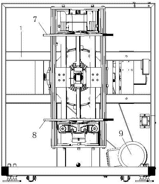
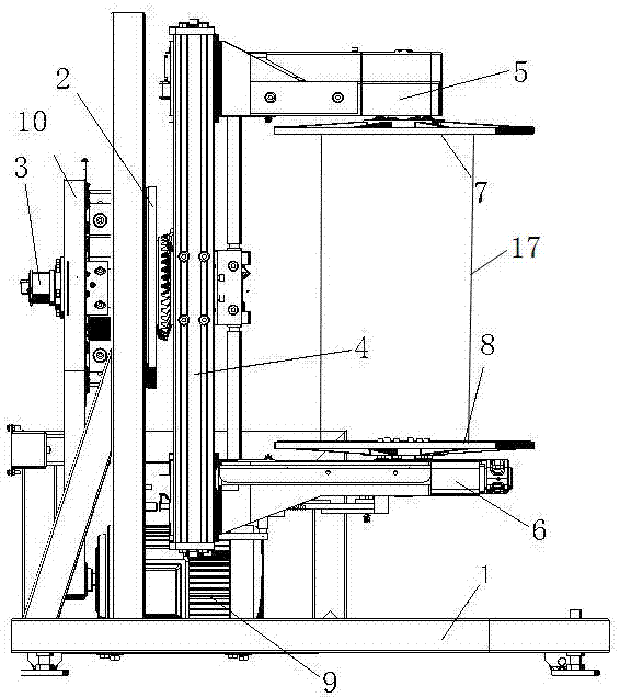
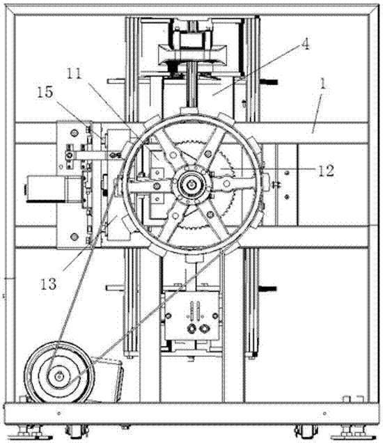
[0028] Example 1, such as Figure 1-7 As shown, when the paint bucket 17 needs to be compressed, a code disc for measuring the position and rotating speed is installed on the driving wheel 10 at the same time, and the rotational position and rotating speed of the driving wheel 10 are measured by the code disc, and the push block 3 is controlled to start moving forward at an appropriate time. move. The driving mechanism on the frame 1 is driven by pneumatic push rod, hydraulic push rod, electric push rod or motor worm to push the push block 13 to press the locking block 11 forward on the slide rail 15. At this time, the rotary main shaft 2 is locked, and the push Block 13 compresses the locking block 11, and the return spring 16 end between the locking block 11 and the shifting gear rod 14 is pressed on the locking block 11 by the pushing block 13, and the other end of the shifting gear rod 14 is connected to the locking gear. 12 separates, and the rotary main shaft 2 can not ...

Embodiment 2

[0030] Example 2, such as Figure 8 As shown, the position of the locking gear 12 is set on one side of the driving wheel 10, the locking gear 12 is set as an external gear, and the working position of the gear rod 14 is set to be consistent with that of the locking gear 12, the above actions can also be completed .

Embodiment 3

[0031] Example 3, such as Figure 9 As shown, the position of the locking gear 12 is set on one side of the driving wheel 10, the locking gear 12 is set as an internal gear, the working position of the shift lever 14 is set to be consistent with the locking gear 12, and the push block 13 is pressed When the locking block 11 is tightened, the gear rod 14 is pressed apart from the internal tooth meshing end of the locking gear 12, and the above-mentioned actions can be completed in cooperation with the above-mentioned components.


PUM


Abstract

The invention relates to a transmission mechanism applicable to a double-rotation coating mixing machine. The transmission mechanism comprises a rotary main shaft, a compression main shaft, a guide rail frame, an upper support arm, a lower support arm, an upper pressure disc and a lower pressure disc, wherein the rotary main shaft is mounted on the stander, the compression main shaft penetrates into the rotary main shaft, the guide rail frame is fixed at the front end of the rotary main shaft, the upper support arm and the lower support arm are arranged eon the guide rail frame and can move up and down in different opposite directions along the guide rail frame, and the upper pressure disc and the lower pressure disc are respectively mounted on the upper support arm and the lower support arm and can rotate; and the rotary main shaft can be used for driving the whole guide rail frame to rotate along the axis of the rotary main shaft and simultaneously driving the upper pressure disc to rotate around the axis through a driving system. The transmission mechanism applicable to the double-rotation coating mixing machine is simple and reasonable in structure and is arranged on the double-rotation coating mixing machine, and by virtue of the action of a driving disc locking device, two independent works including the independent rotation of the compression main shaft and the synchronous rotation of the compression main shaft and the rotary main shaft are independently finished through the driving of a motor.

Description

technical field [0001] The invention relates to a double-rotary mixer for paints, paints and the like, in particular to a transmission mechanism on the double-rotary paint mixer which can make the paint buckets compacted and then mixed. Background technique [0002] At present, mixers in the paint industry are divided into vibratory mixers and rotary mixers (that is, rotary mixers). The present invention relates to a rotary mixer, specifically an automatic double-rotary mixer. machine. Double-rotary mixer is a kind of equipment for mixing or mixing paint, paint and the like, which can make the bucket containing paint, paint and the like The homogenizer rotates around the geometric center line of the paint bucket and at the same time it rotates around the rotation axis perpendicular to the geometric center line of the bucket, that is, it rotates and revolves at the same time to achieve the purpose of double-circular mixing of paint. Patent No. CN200810049422.2 is an inventi...

Claims


Application Information

Patent Timeline
Patent Type & Authority Applications(China)
IPC IPC(8): B01F15/00B01F23/47
CPCB01F35/322B01F35/3204B01F2101/30B01F29/10B01F35/423B01F27/806B01F23/47B01F27/11B01F35/41
Inventor 黄松薛耀斌袁福明
Owner ZHENGZHOU SANHUA TECH & IND
Learn More