Motor fan housing

A technology of air hood and shroud, which is applied in the direction of casing/cover/support, electrical components, electromechanical devices, etc., can solve the problem of low coaxial accuracy between fan and suction nozzle, aggravate ventilation eddy current noise, and affect motor cooling. Heat dissipation and other problems, to achieve good diversion effect, avoid eddy current, and enhance the effect of efficiency

Pending Publication Date: 2017-11-21
WOLONG ELECTRIC GRP CO LTD +1
View PDF6 Cites 1 Cited by
  • Summary
  • Abstract
  • Description
  • Claims
  • Application Information

AI Technical Summary

Problems solved by technology

Obviously, in the current windshield structure, even if the interference between the suction nozzle and the fan blade is avoided, the result of low coaxiality accuracy between the two cannot be avoided
The coaxiality accuracy of the fan and the suction nozzle is low. When the motor is running, the fan rotates, which will form eddy currents, resulting in low fan efficiency, affecting the cooling and heat dissipation of the motor, and aggravating the eddy current noise of the ventilation.
And for this windshield structure, when the fan rotates with the motor shaft, the wind enters the windshield from the rear end, part of the wind flows out from the front end of the windshield tube, and then flows through the cooling fins on the surface of the machine base to cool the motor, and the other part of the wind is It will circulate inside the windshield, forming a vortex, causing losses, resulting in low fan efficiency and loud ventilation noise
[0005] In short, due to the unreasonable connection between the current windshield structure and the rear end cover of the motor, and the unstable structure of the windshield itself, there are disadvantages such as low ventilation efficiency, large ventilation noise, and easy interference with the fan.

Method used


Image

  • Motor fan housing
  • Motor fan housing
  • Motor fan housing

Examples


Embodiment Construction

[0043] In order to make the technical purpose, technical solution and beneficial effect of the present invention clearer, the technical solution of the present invention will be further described below in conjunction with the drawings and specific embodiments.

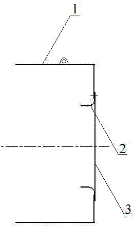
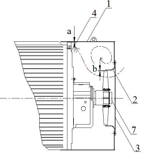
[0044] Such as Figures 1 to 18As shown, a kind of motor fan cover is arranged on the rear end cover 4 of the motor 5, and some straps 16 are evenly distributed on the outer circumference of the rear end cover 4 (the straps are the rear end cover distributed along the outer circumference direction). Several protrusions), the fuselage of the motor 5 is provided with some cooling fins 6 to increase the cooling area and improve the cooling effect of the motor. Described motor wind shield comprises wind shield barrel 1, and wind shield barrel 1 is coaxially provided with conical flow guide cover 12, and flow guide cover 12 adopts perforated plate to be made, and the large-diameter end of described flow guide cover 12 is co...


PUM


Abstract

The invention provides a motor fan housing which is arranged at a rear end cover of a motor. A plurality of lugs are uniformly distributed on the outer circumference of the rear end cover. The motor fan housing includes a fan housing cylinder. A circular truncated cone shaped deflector shield is coaxially arranged in the fan housing cylinder. The large-diameter end of the deflector shield is connected with the rear end of the fan housing cylinder. A fan is coaxially arranged in the deflector shield, and the rotating shaft of the fan is coaxially connected with the motor shaft. The front end of the fan housing cylinder is coaxially sleeved with a flange which is fixedly connected with the outer circumference of the fan housing cylinder. The front end face of the flange is adhered to the rear end faces of the lugs, and the flange and the lugs are connected through rabbet fit. The coaxiality between the fan housing cylinder and the fan is ensured. Vortex flow is avoided. The efficiency of the fan is improved. The motor cooling capacity is improved. The ventilation noise is reduced.

Description

technical field [0001] The invention belongs to the technical field of motor wind shields, and in particular relates to a motor wind shield. Background technique [0002] The cooling method is the cylindrical motor with IC411 structure (fully enclosed, self-contained fan cooling), the rear end of the rotating shaft of the motor is equipped with an external fan, and the outer fan is equipped with a windshield connected with the rear end cover of the motor , to form an external air path that flows from the back to the front. When the external air path flows through the surface of the motor frame, it takes away the surface heat to achieve the effect of cooling the motor. Common hoods are mainly composed of hood tubes, suction nozzles, and net windows, such as figure 1 As shown, the rear end of the windshield tube 1 is provided with a rear side wall, and a suction port is coaxially provided on the rear side wall, and a suction nozzle is coaxially arranged in the suction port; t...

Claims


Application Information

Patent Timeline
Patent Type & Authority Applications(China)
IPC IPC(8): H02K5/04H02K5/24
CPCH02K5/04H02K5/24
Inventor 甘方熹张东波王乾张明娟柳忠雨高建奇王晓俊
Owner WOLONG ELECTRIC GRP CO LTD
Why Eureka
Try Eureka