
Train shaking factor detection device and method

A detection device and train technology, applied in the field of rail transit, can solve the problems of inability to locate and locate objects, low detection accuracy and reliability, and discrete data, so as to save instrument costs and labor costs, and to achieve detection accuracy and reliability. High performance to meet maintenance needs

Active Publication Date: 2017-11-21
SOUTHWEST JIAOTONG UNIV
View PDF8 Cites 2 Cited by
  • Summary
  • Abstract
  • Description
  • Claims
  • Application Information

AI Technical Summary

Problems solved by technology

The detection method is to realize the evaluation of the service state of the train through the measurement data through the simple Sperling index (railway train running stability index) and the effective value of the acceleration, and evaluate the smoothness of the track according to the evaluation results, and add the riding instrument, shake the car The instrument only considers the vertical and lateral vibration of the train (without considering the longitudinal vibration acceleration), the detection accuracy and reliability are low; moreover, the data source is single and the collected data is very discrete, and it does not consider the use of multiple trains or multiple Multi-data fusion analysis is carried out on the swaying data of the track section. For the evaluation of the service state of high-speed trains and the evaluation of track smoothness, the data analysis and processing methods are backward, and it is impossible to accurately locate the uneven positions and objects, which is difficult to meet Increasing demand for maintenance and repair of high-speed railways

Method used

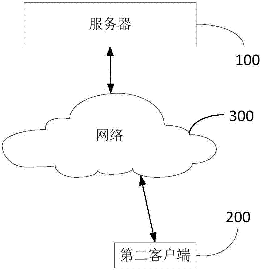
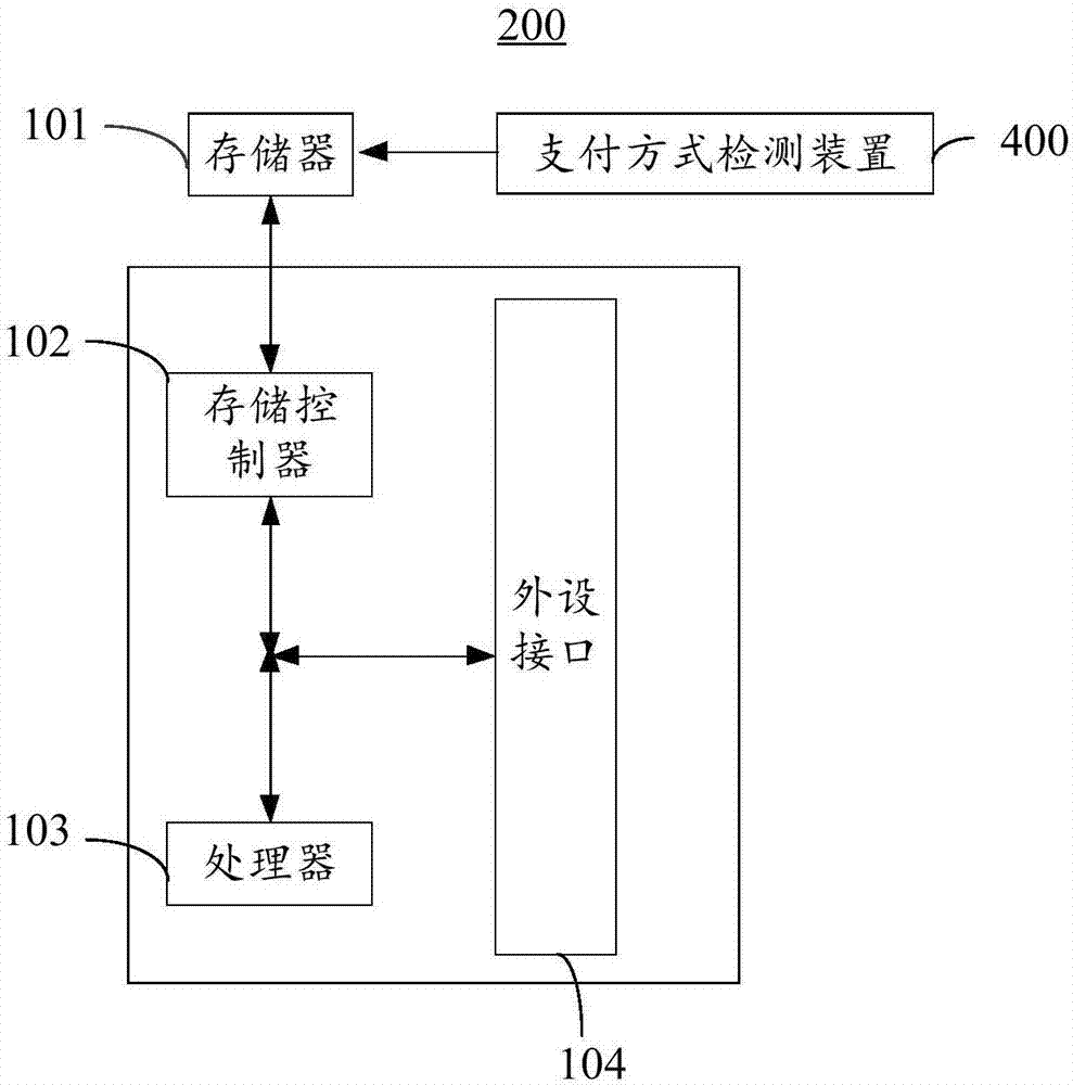

Image

  • Train shaking factor detection device and method
  • Train shaking factor detection device and method
  • Train shaking factor detection device and method

Examples


Embodiment Construction

[0022] The following will clearly and completely describe the technical solutions in the embodiments of the present invention with reference to the accompanying drawings in the embodiments of the present invention. Obviously, the described embodiments are only some, not all, embodiments of the present invention. The components of the embodiments of the invention generally described and illustrated in the figures herein may be arranged and designed in a variety of different configurations. Accordingly, the following detailed description of the embodiments of the invention provided in the accompanying drawings is not intended to limit the scope of the claimed invention, but merely represents selected embodiments of the invention. Based on the embodiments of the present invention, all other embodiments obtained by those skilled in the art without making creative efforts belong to the protection scope of the present invention.

[0023] The train shaking factor detection device and...


PUM


Abstract

The invention provides a train shaking factor detection device and method, and relates to the field of rail transit. Received first acceleration information of a plurality of first three-dimensional coordinate systems built along screens of intelligent terminals is converted into multiple pieces of second acceleration information of a second three-dimensional coordinate system with each train running direction as the Y axis, wherein each train is provided with a plurality of intelligent terminals moving along with the train; according to the second acceleration information, multiple pieces of train identity information and multiple pieces of position information of the intelligent terminals, shaking factor results are generated. Detection instruments do not need to be installed on the trains, the requirements of detection equipment for placement and installation postures are eliminated, dependence on the installed detection instruments in the prior art is broken through, the cost is reduced, vibration in the vertical direction and in the transverse direction of the trains are considered, vibration conditions of the trains in the longitudinal direction, namely the training running directions, are also considered, detection precision and reliability are high, and unsmooth positions and objects are precisely positioned.

Description

technical field [0001] The invention relates to the field of rail transit, in particular to a device and method for detecting train shaking factors. Background technique [0002] With the gradual formation of my country's high-speed railway network, the pressure of line maintenance and repair is gradually increasing. Accurately grasping the running state of trains can provide a basis for vehicle maintenance on the one hand, and is also an important basis for maintenance and repair of railway lines on the other hand. Among them, the accurate, extensive and convenient detection of train body acceleration has become a new research hotspot. [0003] In the prior art, the monitoring of the service state of railway trains and the evaluation of track smoothness mainly rely on special testing equipment, such as adding ride testers, car shaking testers, etc. The monitoring of the service status of railway trains and the evaluation of track smoothness in the prior art require high co...

Claims


Application Information

Patent Timeline
IPC IPC(8): G06F17/16G06F17/18G07C5/08
CPCG06F17/16G06F17/18G07C5/0841
Inventor 王平王源
Owner SOUTHWEST JIAOTONG UNIV
Learn More