
Strip material cut-off mechanism

A cutting mechanism and strip material technology, which is applied in the cutting of textile materials, textiles and paper making, etc., can solve the problems of complex structure, troublesome operation, adjustment of the length of strip material cutting, etc., and achieve the effect of reasonable structural design

Active Publication Date: 2017-11-21
盐城市星地通信设备有限公司
View PDF7 Cites 4 Cited by
  • Summary
  • Abstract
  • Description
  • Claims
  • Application Information

AI Technical Summary

Problems solved by technology

In the production process of the strip, it is necessary to continuously cut the strip according to the needs of use, so that the strip processed by the previous process can be cut into multiple sections, which is convenient for the subsequent process to process. The existing strip The structure of the cutting mechanism is complicated and the operation is cumbersome. It is difficult to cut the strip continuously and uniformly accurately and efficiently during use, making it difficult to keep the length of each section of the strip consistent during the cutting process. The existing strip cutting mechanism is During use, it is difficult to adjust the length of strip cutting according to the needs of strip production and processing, and in the process of using the existing strip cutting mechanism, once the strip cutting fails or there is a safety hazard in the cutting process, the existing strip cutting mechanism will It is difficult for the cutting mechanism to stop the cutting action quickly. Even if the cutting motor is stopped immediately, the cutting motor will continue to drive the cutting blade to perform the cutting action due to the rotational inertia during the process of stopping the rotation, which cannot meet the needs of production and use.

Method used


Image

  • Strip material cut-off mechanism
  • Strip material cut-off mechanism

Examples


Embodiment Construction

[0011] In order to further describe the present invention, a specific implementation of a tape cutting mechanism will be further described below in conjunction with the accompanying drawings. The following examples are explanations of the present invention and the present invention is not limited to the following examples.

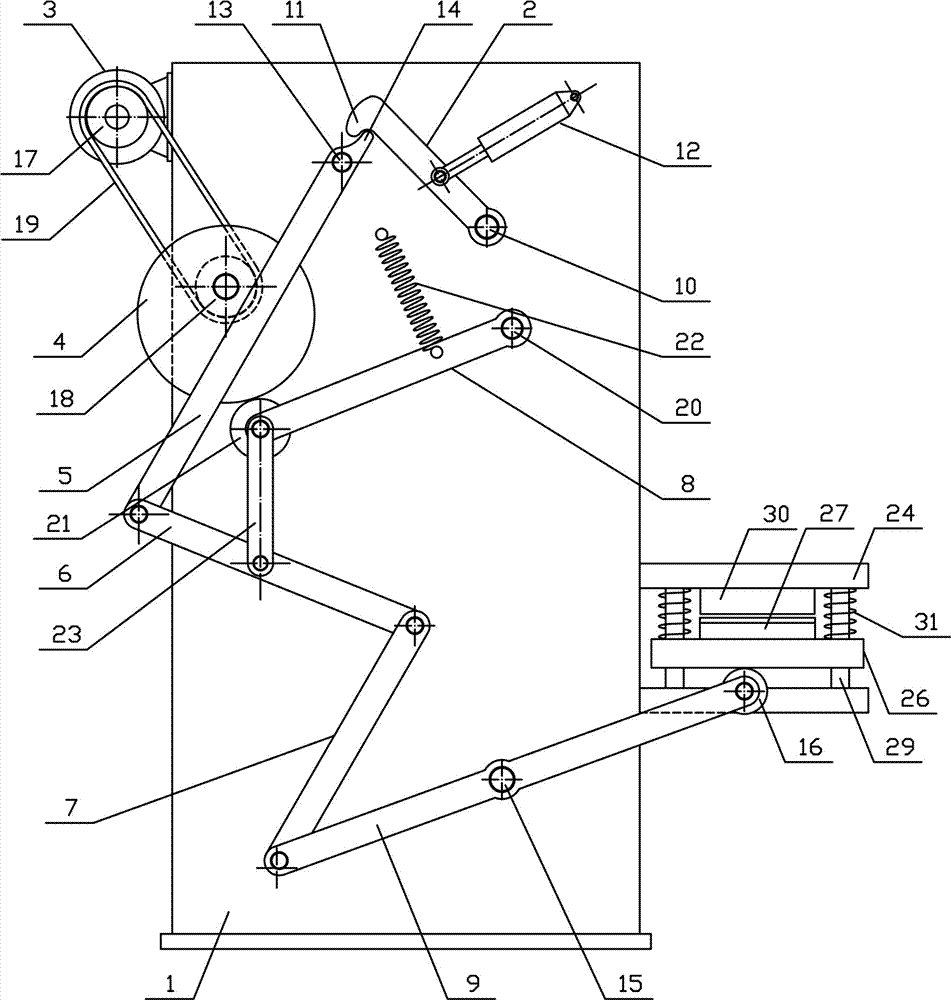
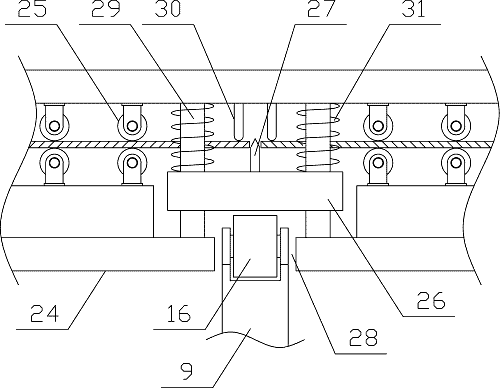
[0012] like figure 1 As shown, a strip cutting mechanism of the present invention includes a fixed bracket 1, a limit clamp plate 2, a strip cutting motor 3, a strip cutting eccentric wheel 4, a first rotating plate 5, a second rotating plate 6, and a third rotating plate. Plate 7, reciprocating rotating plate 8, belt cutting and pressing plate 9 and belt guide mechanism, the belt guide mechanism of the present invention is horizontally arranged on one side of the fixed bracket 1, and the side above the fixed bracket 1 is horizontally rotated and provided with a first fixed shaft 10, and the limit The clamping plate 2 is obliquely arranged on one side of t...


PUM


Abstract

The invention discloses a strip material cut-off mechanism and belongs to the field of textile materials processing mechanical equipment. The strip material cut-off mechanism comprises a fixing bracket, a limiting clamp plate, a strip cutting motor, a strip cutting eccentric wheel, a first rotary plate, a second rotary plate, a third rotary plate, a reciprocating plate, a strip cutting pressing plate and a strip guide mechanism. The strip guide mechanism is horizontally arranged on one side of the fixing bracket, a clamp plate air cylinder is arranged between the limiting clamp plate and the fixing bracket, the strip cutting eccentric wheel is vertically and rotationally connected with one side on the upper portion of the fixing bracket, a tension spring is arranged between the upper side of the reciprocating plate and the fixing bracket, a strip cutting connecting rod is arranged between the lower end of the reciprocating plate and the second rotary plate, and the strip guide mechanism comprises a strip guide support, strip guide rollers, a lifting press plate and a strip cutting knife blade. The strip material cut-off mechanism is reasonable in structural design, transverse cutting can be quickly, efficiently, uniformly and continuously conducted in the conveying process of strip materials, the cut-off movement can be quickly and conveniently stopped in the use process, and the production use requirements are met.

Description

technical field [0001] The invention belongs to the field of textile material processing machinery and equipment, in particular to a strip material cutting mechanism. Background technique [0002] Strip refers to a flat long strip material. According to the material, the strip can be divided into metal strip and textile strip. Textile strip is widely used in our daily production and life. Textile strip is mainly It is woven with chemical fiber materials. The strip is generally made of high-strength nylon filaments. It has multiple advantages of high strength, wear resistance, oxidation resistance, and UV resistance. At the same time, it is soft, non-conductive, and non-corrosive. It is widely used in various fields. , the strip is a kind of rigging, there are many types, generally divided into four types: annular core, annular flat, double eye core and double eye flat. During the selection process of the strip, the conventional strip can be directly selected. For special use...

Claims


Application Information

Patent Timeline
IPC IPC(8): D06H7/00
CPCD06H7/00
Inventor 张帼威
Owner 盐城市星地通信设备有限公司
Learn More