Material conveying device with cleaning function

A transmission device and functional technology, applied in the field of material transmission device with cleaning function, can solve the problems of easy material blocking, large impact of material receiving belt, material waste, etc., to reduce waste and loss, and not easy to accumulate and block materials , the effect of avoiding loss and waste

Inactive Publication Date: 2017-11-21
李汉忠
View PDF2 Cites 1 Cited by
  • Summary
  • Abstract
  • Description
  • Claims
  • Application Information

AI Technical Summary

Problems solved by technology

The existing transfer device has the following defects: 1. The baffle plate 2 adopts the material beating mode, and the material is vertically lowered by 90 degrees without any buffer, which makes it have a greater impact on the material receiving belt and reduces the service life of the material receiving belt
2. Since the head cleaner 7 is installed under the return belt of the feeding belt, the feeding belt is not easy to clean
It is for highly viscous materials, and the return belt with materials will cause pollution to the site environment
3. The head cleaner 7 is installed in the material return area. When cleaning the material, the material on the return belt is easy to splash out of the transfer device, resulting in material waste
4. Under the action of the baffle plate 2, the highly viscous material is easy to block the material and produce material accumulation, which affects the conveying efficiency of the highly viscous material

Method used


Image

  • Material conveying device with cleaning function
  • Material conveying device with cleaning function

Examples


Embodiment Construction

[0017] The present invention will be further described below in conjunction with the accompanying drawings.

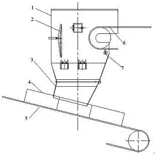
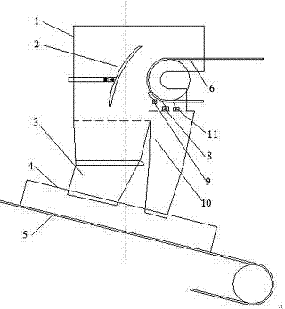
[0018] Such as figure 2 Shown, the present invention comprises funnel 1, feeding belt 6, material blocking plate 2, chute 3, material guide trough 4, the 3rd head cleaner 11, the second head cleaner 8, head main cleaner 9, auxiliary The chute 10 and the material receiving belt 5, the feeding belt 6 stretches into the feeding port of the funnel 1, the upper ends of the chute 3 and the auxiliary chute 10 are connected with the funnel 1, and the lower ends of the chute 3 and the auxiliary chute 10 pass through The material guide groove 4 is connected with the material receiving belt 5 . The hopper 1 is provided with a baffle plate 2, a third head cleaner 11, a second head cleaner 8, and a main head cleaner 9. The baffle plate 2 is located in the hopper 1, facing the redirection of the feeding belt 6. Set at the position, the material retaining plate 2 is arc-shaped, an...


PUM


Abstract

The invention provides a material conveying device with a cleaning function. The material conveying device comprises a funnel, a feeding belt, a striker plate and a receiving belt. The feeding belt stretches to the position of a feeding port of the funnel, the striker plate is located at the position, close to the feeding port, inside the funnel, and the receiving belt is located below a discharging port of the funnel. A head main sweeper, a second head sweeper and a third head sweeper which are used for sweeping a return belt are sequentially arranged below the feeding belt, and the head main sweeper, the second head sweeper and the third head sweeper are arranged in the funnel and are close to the position of the feeding port. The head main sweeper is further provided with a drying device and an electric draught fan. The striker plate is connected with a mechanical arm and used for controlling the angle between the striker plate and the feeding port. The material conveying device is high in efficiency and practicality and easy to popularize.

Description

technical field [0001] The invention belongs to the technical field of bulk material conveying, and in particular relates to a material conveying device with a cleaning function. Background technique [0002] The transfer device is a key position in the bulk material conveying system, carrying the function of material transfer, and is mainly used for material transfer in the fields of metallurgy, port, electric power and chemical industry. The structure of the transfer connection device is mainly composed of a baffle plate, a head funnel, a chute, a material guide trough, a cleaner and other components. [0003] Such as figure 1 As shown, the existing transfer device comprises a funnel 1, a feeding belt 6, a material retaining plate 2, a chute 3, a material guide 4 and a material receiving belt 5, the feeding belt 6 communicates with the funnel 1, and the upper end of the chute 3 is connected to the The funnel is connected, and the lower end is connected with the receiving...

Claims


Application Information

Patent Timeline
Patent Type & Authority Applications(China)
IPC IPC(8): B65G65/32B65G65/42B65G45/24B65D88/28B65D88/54
CPCB65G65/32B65D88/28B65D88/54B65G45/24B65G65/42B65G2201/04B65G2207/26
Inventor 李汉忠
Owner 李汉忠
Why Eureka
Try Eureka