Wireless charging transmitting device, receiving device and wireless charging system
A wireless charging and transmitting device technology, applied in the direction of circuit devices, battery circuit devices, collectors, etc., can solve the problems of wireless charging efficiency reduction, large magnetic loss, magnetic flux leakage, etc., to ensure aesthetic appearance, reduce magnetic resistance and Magnetic flux leakage and the effect of reducing magnetic flux leakage
- Summary
- Abstract
- Description
- Claims
- Application Information
AI Technical Summary
Problems solved by technology
Method used
Image
Examples
Embodiment 1
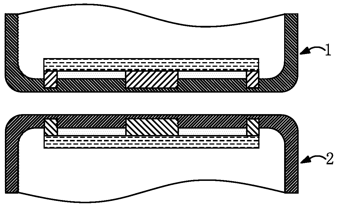
[0040] This embodiment provides a wireless charging system, such as figure 1 As shown, it includes a wireless charging transmitting device 1 and a wireless charging receiving device 2 connected wirelessly, and the wireless charging transmitting device 1 is electrically connected to a power source (not shown in the figure) for transmitting to the wireless charging receiving device 2 through electromagnetic induction or magnetic resonance. For energy, the wireless charging receiving device 2 is electrically connected to a battery (not shown in the figure) for receiving energy from the wireless charging transmitting device 1 and charging the battery.
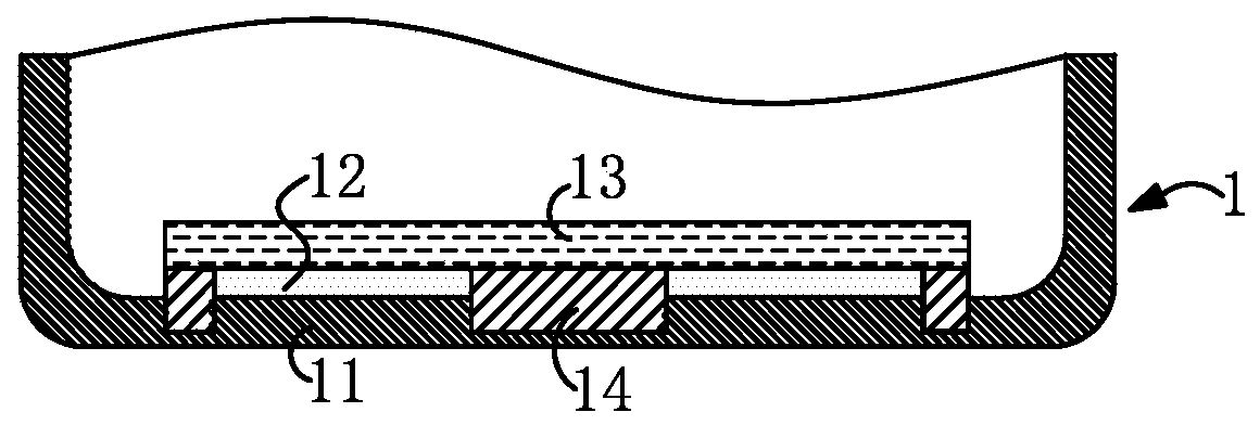
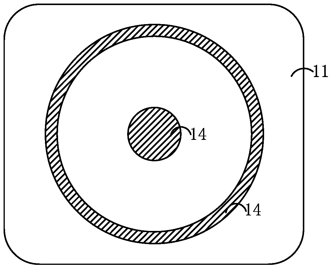
[0041] Specifically, such as figure 2 As shown, the wireless charging transmitting device 1 includes a first housing 11, a transmitting coil 12 assembled on the inner surface of the first housing 11, a first magnetic isolation sheet 13 made of ferrite fixed on the transmitting coil 12, and an embedded A first injection molded fer...
Embodiment 2
[0059] This embodiment provides a wireless charging system, such as Figure 8 As shown, it includes a wireless charging transmitting device 1 and a wireless charging receiving device 2 connected wirelessly, and the wireless charging transmitting device 1 is electrically connected to a power source (not shown in the figure) for transmitting to the wireless charging receiving device 2 through electromagnetic induction or magnetic resonance. For energy, the wireless charging receiving device 2 is electrically connected to a battery (not shown in the figure) for receiving energy from the wireless charging transmitting device 1 and charging the battery.
[0060] Specifically, such as Figure 9 As shown, the wireless charging transmitting device 1 includes a first casing 11, a transmitting coil 12 assembled on the inner surface of the first casing 11, and a first magnetic isolation sheet 13 made of ferrite fixed above the transmitting coil 12, wherein the first A housing 11 is form...
Embodiment 3
[0067] This embodiment provides a wireless charging system, such as Figure 11 As shown, it includes a wireless charging transmitting device 1 and a wireless charging receiving device 2 connected wirelessly, and the wireless charging transmitting device 1 is electrically connected to a power source (not shown in the figure) for transmitting to the wireless charging receiving device 2 through electromagnetic induction or magnetic resonance. For energy, the wireless charging receiving device 2 is electrically connected to a battery (not shown in the figure) for receiving energy from the wireless charging transmitting device 1 and charging the battery.
[0068] The only difference between the wireless charging transmitting device in this embodiment and the wireless charging transmitting device in the first embodiment is that Figure 12 As shown, the lower surface of the first magnetic isolation piece 13 is recessed toward the inside of itself to form a first groove, the upper surfa...
PUM
 Abstract
Description
Claims
Application Information
 - Generate Ideas
- Intellectual Property
- Life Sciences
- Materials
- Tech Scout
- Unparalleled Data Quality
- Higher Quality Content
- 60% Fewer Hallucinations
Browse by: Latest US Patents, China's latest patents, Technical Efficacy Thesaurus, Application Domain, Technology Topic, Popular Technical Reports.
© 2025 PatSnap. All rights reserved.Legal|Privacy policy|Modern Slavery Act Transparency Statement|Sitemap|About US| Contact US: help@patsnap.com


