Filling and sealing structure of axially split pump

A technology of sealing structure and pump body, which is applied to the components, pumps, and pump components of pumping devices for elastic fluids, can solve the problems of easy mechanical fatigue, shortened bearing life, easy heating of bearings, etc., and achieves safety. High stability, reduced leakage, and improved sealing effect

Inactive Publication Date: 2017-11-17
王道红
View PDF4 Cites 0 Cited by
  • Summary
  • Abstract
  • Description
  • Claims
  • Application Information

AI Technical Summary

Problems solved by technology

[0003] The existing split pumps generally purchase S and SH type split pump structures. Due to the special hydraulic model of the split pump, the water flow is sucked into the impeller from both sides of the impeller at the same time, so the suction chamber is wider, resulting in a larger bearing span. When the bearing span When the distance is large, the radial force generated by the impeller will act on the shaft when the pump is running, forming a large deflection. The larger the bearing span, the greater the deflection; the shaft is prone to mechanical fatigue after deformation due to deflection ;The bearing will also be in an abnormal stress state due to the deflection generated by the shaft, so the bearing is prone to heat, the bearing life is shortened, and even serious product quality problems such as broken shaft occur.

Method used


Image

  • Filling and sealing structure of axially split pump
  • Filling and sealing structure of axially split pump

Examples


Embodiment Construction

[0022] In order to enable those skilled in the art to better understand the technical solution of the present invention, the present invention will be described in detail below in conjunction with the accompanying drawings. The description in this part is only exemplary and explanatory, and should not have any limiting effect on the protection scope of the present invention. .

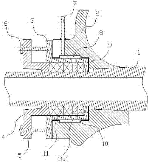
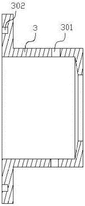
[0023] Such as Figure 1-Figure 2 As shown, the structure of the present invention is: a filling and sealing structure of a split pump, which includes a shaft sleeve 1 arranged on the shaft, a pump body 2 is arranged on the shaft sleeve 1, and the shaft sleeve 1 The upper sleeve is connected with a stuffing retainer 3 docked with the outside of the pump body 2, and the stuffing retainer 3 is connected with a packing gland 4 matched with it, and a sealed cavity is formed between the packing gland 4 and the stuffing retainer 3, so The packing ring 10 and the packing 11 are arranged in the sealing cavity...


PUM


Abstract

The invention relates to the sealing field of split pumps, in particular to a filling and sealing structure of split pumps, which includes a shaft sleeve arranged on a shaft, a pump body is arranged on the shaft sleeve, and a There is a packing retainer docked with the outside of the pump body, the packing retainer is connected with a packing gland matching it, and a sealing cavity is formed between the packing gland and the packing retaining sleeve, and a packing ring is arranged in the sealing cavity and packing, the packing ring and the flushing hole provided on the stuffing retainer butt, the outer side of the packing retaining sleeve is provided with a water tank communicating with the flushing hole, and the water tank communicates with the flushing pipe; the purpose of the present invention is Provide a filling and sealing structure for split pumps, set a cylindrical packing retainer, and set a water tank connected to it on the outside of the packing retainer, and connect the water tank to the washing pipe to make the position of the sealing chamber closer The impeller is improved, the bearing span is reduced, and the deflection of the shaft is guaranteed to be in a safe range.

Description

technical field [0001] The invention relates to the sealing field of split pumps, in particular to a filling and sealing structure of split pumps. Background technique [0002] A split pump is a hydraulic component that converts a low-pressure medium into a high-pressure medium. Therefore, good sealing is required, and the seal of the pump body is an important part of the split pump seal. [0003] The existing split pumps generally purchase S and SH type split pump structures. Due to the special hydraulic model of the split pump, the water flow is sucked into the impeller from both sides of the impeller at the same time, so the suction chamber is wider, resulting in a larger bearing span. When the bearing span When the distance is large, the radial force generated by the impeller will act on the shaft when the pump is running, forming a large deflection. The larger the bearing span, the greater the deflection; the shaft is prone to mechanical fatigue after deformation due to...

Claims


Application Information

Patent Timeline
Patent Type & Authority Applications(China)
IPC IPC(8): F04D29/08
CPCF04D29/086
Inventor 王道红
Owner 王道红
Why Eureka
Try Eureka