
Processing method for valve assembly

A technology of valve components and processing methods, applied in the field of T-shaped valve stems, can solve the problems of no identical or similar technical solutions, quality not meeting the requirements, loose organization, etc., achieve less cutting, improve product production efficiency, and step simple effect

Inactive Publication Date: 2017-11-17
RUGAO CITY SHUANGYA ENVIRONMENTAL PROTECTION TECH CO LTD
View PDF8 Cites 5 Cited by
  • Summary
  • Abstract
  • Description
  • Claims
  • Application Information

AI Technical Summary

Problems solved by technology

[0005] At present, there are two ways to produce the above-mentioned T-shaped valve stem: one is the method of casting, and its disadvantages are: the internal structure is loose, there are shrinkage holes, cracks and other defects, the quality does not meet the requirements, and there are large safety hazards , and more waste
After retrieving relevant documents, no technical solutions identical or similar to the present invention have been found

Method used


Image

  • Processing method for valve assembly
  • Processing method for valve assembly
  • Processing method for valve assembly

Examples


Embodiment 1

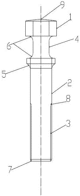
[0025] Such as figure 1 As shown, the valve assembly of the present invention is a valve stem, specifically a T-shaped valve stem. The groove 4, the connection between the head 1 and the polished rod part 2 is an arc-shaped sealing surface 5; the upper and lower ends of the trapezoidal groove 4 have circular arc chamfers 6, and the end of the threaded part 3 has circular arc chamfers 7, and the polished rod part 2 has an arc chamfer 8 at the joint with the threaded part 3; the upper end surface of the head 1 is an arc-shaped convex surface 9.

[0026] In this embodiment, the T-shaped valve stem, the upper and lower ends of the trapezoidal groove and the end of the threaded part all have arc chamfers, and the sealing surface is arc-shaped. The original right-angle chamfers are set as arc chamfers, which is convenient Die forging is basically one-time forming, which reduces the processing steps, and the stress of the arc chamfering is more uniform, which improves the service li...

Embodiment 2

[0040] In this embodiment, on the basis of Embodiment 1, the round bar stock in step (1) adopts bearing round steel;

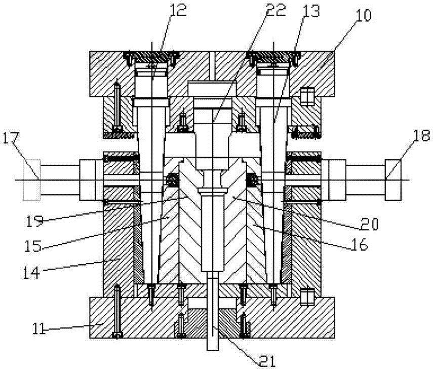
[0041] The ends of the piston rods of the left and right female mold locking cylinders in the special forging die are tapered or wedge-shaped, and the outer surfaces of the left and right female molds are provided with tapered or wedge-shaped holes that match the piston rods of the left and right female mold locking cylinders. wedge-shaped structure.

[0042] In this embodiment, the bearing round steel is used as the round bar, which has high hardness, and the hardness of the formed T-shaped valve stem reaches HRC186-230; in the special forging mold, the piston rod ends of the left and right female mold locking cylinders The upper part is a tapered or wedge-shaped structure, which improves the locking structure of the forging die, thus ensuring the smooth forging of the product.


PUM


Abstract

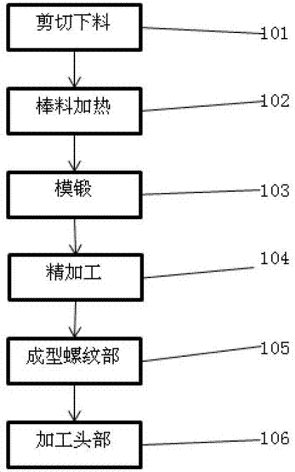
The invention relates to a T-shaped valve rod, a processing method thereof and a special forging and pressing die. The valve rod is a rod-like body and comprises a head, a central polish rod part and a threaded part; a trapezoidal slot is formed in each of the left and right sides of the head, a sealing surface is formed at the junction of the head and the polish rod part, the upper and lower ends of the trapezoidal slots, the junctions of the polish rod part and the threaded part and the ends of the threaded part are arc chamfers, and the sealing surface is arc-shaped; and the upper end surface of the head is an arc-shaped convex surface. The processing method of the valve assembly sequentially comprises the steps: shearing and blanking, heating, die forging, finishing, threaded part forming and head processing. The T-shaped valve rod disclosed by the invention has the advantages of simple processing process, capability of realizing little cutting and even no cutting, reducing the cost and increasing the production efficiency of a product and low material consumption.

Description

technical field [0001] The invention relates to a T-shaped valve stem, in particular to a processing method for a valve assembly. Background technique [0002] The valve stem is an important part of the valve. It is used for transmission. The upper part is connected to the actuator or the handle, and the lower part directly drives the valve core to move or rotate to realize the valve switch or adjustment function. [0003] The valve stem is not only a moving part, a stressed part, but also a sealing part during the opening and closing process of the valve. At the same time, it is impacted and corroded by the medium, and also has friction with the filler. Therefore, when selecting the material of the valve stem, it must be ensured that it has sufficient strength, good impact toughness, scratch resistance, and corrosion resistance at the specified temperature. The valve stem is a vulnerable part, and the machining performance and heat treatment performance of the material sh...

Claims


Application Information

Patent Timeline
Patent Type & Authority Applications(China)
IPC IPC(8): B23P15/00
CPCB23P15/001
Inventor 左逸凡
Owner RUGAO CITY SHUANGYA ENVIRONMENTAL PROTECTION TECH CO LTD
Learn More