
Cyclone type flue gas dust removal device

A dust removal device and cyclone-type technology, which is applied to the separation of dispersed particles, chemical instruments and methods, separation methods, etc., can solve the problems of insignificant cyclone effect and unsatisfactory dust removal effect, and achieve simple structure, low manufacturing cost, Ease of use

Pending Publication Date: 2017-11-17
SHENZHEN ENERGY ENVIRONMENT ENG
View PDF8 Cites 8 Cited by
  • Summary
  • Abstract
  • Description
  • Claims
  • Application Information

AI Technical Summary

Problems solved by technology

[0004] The problem is that in the existing flue gas dust removal device, the effect of the swirling flow is not obvious, so the dust removal effect is not ideal

Method used


Image

  • Cyclone type flue gas dust removal device
  • Cyclone type flue gas dust removal device

Examples


Embodiment Construction

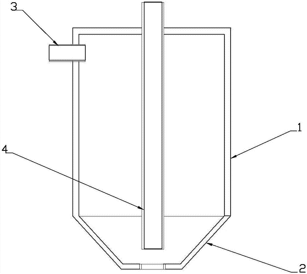
[0012] figure 1 It is a structural schematic diagram of an embodiment of the prior art. As shown in the figure, the existing flue gas dust removal equipment includes a casing 1 and an ash hopper 2 arranged on the lower side of the casing. The pipe 4 is connected to the chamber from the upper side of the housing 1 and extends to the bottom of the chamber 1.1. The smoke enters the upper part of the chamber 1.1 from the air inlet pipe 3 and forms a certain swirl flow from the outlet pipe 4 at the lower part of the chamber 1.1. When the flue gas forms a swirling flow, the larger particles in the flue gas are thrown to the wall of the cavity due to the centrifugal force, and finally discharged from the ash falling port 2.1 at the lower end of the ash hopper 2.

[0013] In the prior art, the swirling effect of the flue gas dedusting device is not obvious, so the dedusting effect is not ideal.

[0014] figure 2 It is a structural schematic diagram of an embodiment proposed by the...


PUM


Abstract

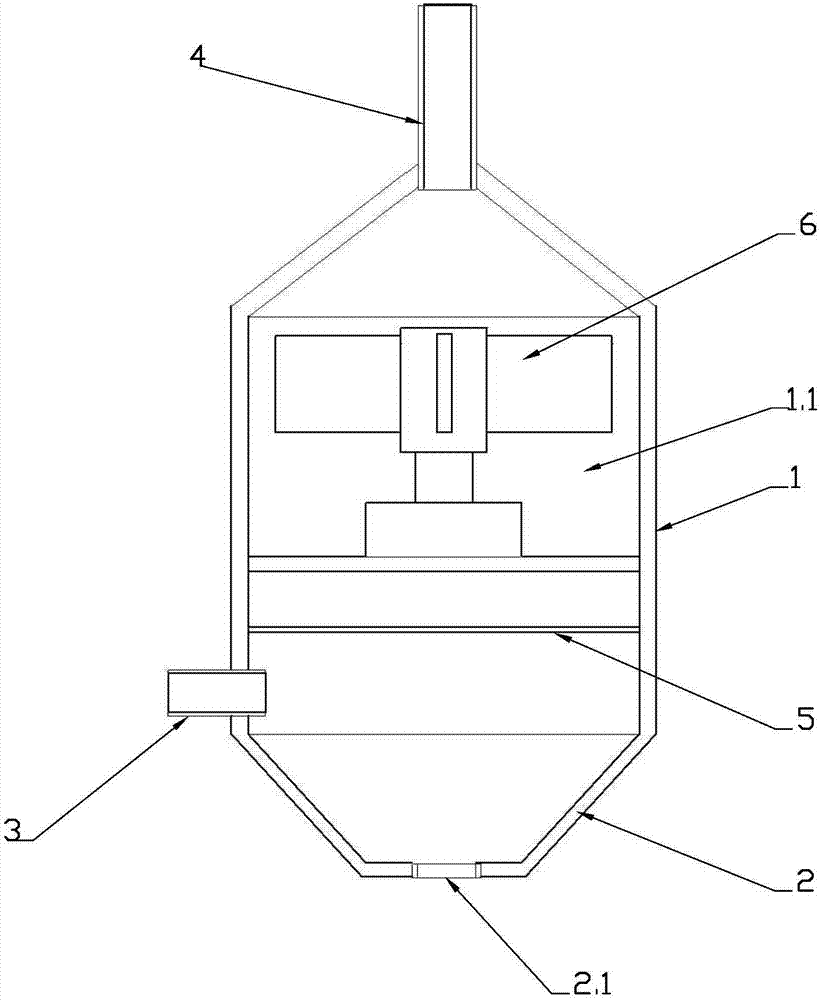
An existing flue gas dust removal device comprises a casing and an ash bucket arranged on the lower side of the casing, wherein an air inlet pipe is connected into a cavity of the casing from the upper side of the casing; an air outlet pipe is connected into the cavity from the upper side of the casing and extends to the bottom of the cavity; flue gas enters the upper part of the cavity from the air inlet pipe, rotational flow is formed and enters the air outlet pipe from an air outlet pipe orifice at the lower part of the cavity, and when the flue gas forms the rotational flow, relatively large particles in the flue gas are thrown to the wall of the cavity under the action of centrifugal force and discharged from an ash falling port in the lower end of the ash bucket. To solve the existing technical problem, the invention provides the cyclone type flue gas dust removal device. The device comprises the casing, the ash bucket, the air inlet pipe and the air outlet pipe and is characterized in that a fan is further arranged in the casing and supplies air from bottom to up, the air inlet pipe is arranged on the lower side of the fan, the air outlet pipe is arranged on the upper side of the fan, and a filter net is further arranged on the upper side of the air inlet pipe. Due to arrangement of the fan, the cyclone effect of flue gas in the cavity is better, and the flue gas dust treatment capacity is further improved.

Description

technical field [0001] The invention relates to flue gas treatment equipment, in particular to a cyclone type flue gas dust removal device. Background technique [0002] Among the many performance indicators of cyclone dust collectors, pressure loss and separation efficiency have always been concerned by cyclone dust collector researchers. How to improve the efficiency of cyclone dust collectors while achieving reasonable pressure loss has always been the common concern of researchers at home and abroad. hot spot. In recent years, my country's smoke and dust emission standards have gradually become stricter, and more and more attention has been paid to the control of inhalable particulate matter emission standards in the atmosphere. These all reflect the importance of improving the separation efficiency of dust particles. [0003] The existing flue gas dust removal equipment includes a shell and an ash hopper arranged on the lower side of the shell. The air inlet pipe is co...

Claims


Application Information

Patent Timeline
Patent Type & Authority Applications(China)
IPC IPC(8): B01D45/16
CPCB01D45/16
Inventor 刘双平何少敦
Owner SHENZHEN ENERGY ENVIRONMENT ENG
Learn More