
Device for cutting hair, floor drain with device and working method of device

A hair and assembly technology, applied in water supply installations, waterway systems, buildings, etc., can solve the problems of manual start, product failure, inconvenient installation and use, etc., to achieve convenient installation and use, improve utilization, and good shearing effect. Effect

Inactive Publication Date: 2017-11-14
JOMOO KITCHEN & BATHROOM
View PDF4 Cites 13 Cited by
  • Summary
  • Abstract
  • Description
  • Claims
  • Application Information

AI Technical Summary

Problems solved by technology

[0002] The existing floor drain cannot cut hair and is easy to block, such as figure 1 As shown, the fixed part (10') fixed on the ground is provided with an assembly hole (11'), and only a filter screen (12') is arranged in the assembly hole; or the structure with the function of cutting hair is very complicated and needs to be started manually or by feet. It is very inconvenient to install and use; and the existing method of cutting hair basically relies on the rotation of the blade to form a cutting effect, but the disadvantage of rotation is that it is easy to make the hair entangled on the rotating shaft, making the product fail

Method used


Image

  • Device for cutting hair, floor drain with device and working method of device
  • Device for cutting hair, floor drain with device and working method of device
  • Device for cutting hair, floor drain with device and working method of device

Examples


Embodiment Construction

[0042] The present invention will be further described below through specific embodiments.

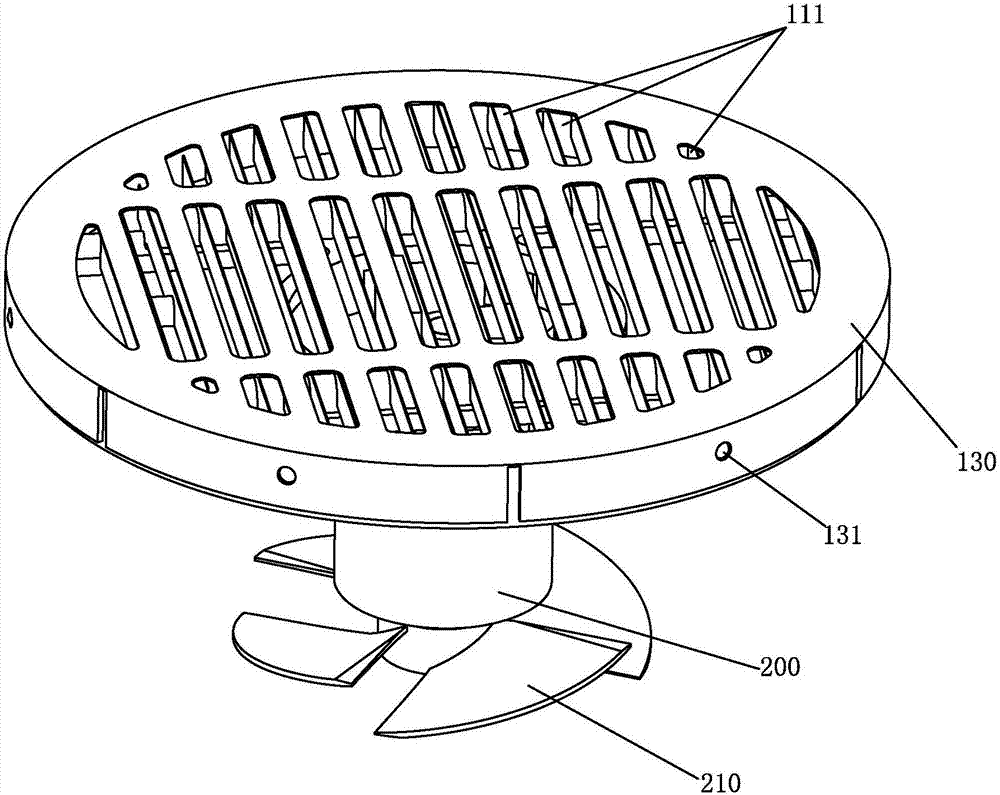
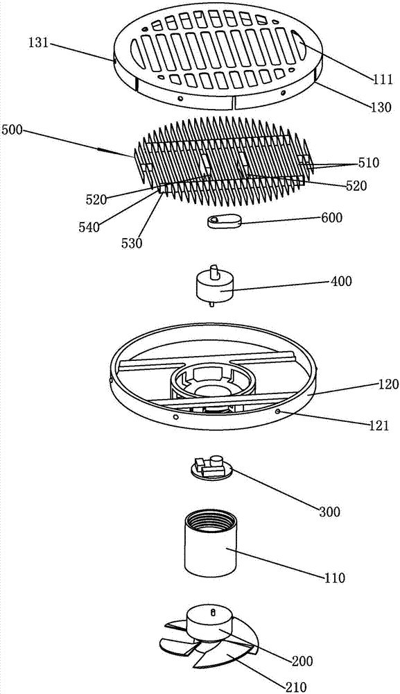
[0043] refer to Figure 2 to Figure 11 , a device for cutting hair, which includes a housing, a hydroelectric generator 200, a circuit board 300, a rotating motor 400 and a blade assembly 500.

[0044] The housing is provided with a water hole 111 . In this embodiment, the housing is further provided with guide rails 112 . In this embodiment, there are two guide rails 112 arranged front and rear.

[0045] In this embodiment, the housing includes a mask 130 , a frame 120 and a sleeve 110 which are sequentially connected up and down.

[0046] In this embodiment, the sleeve 110 and the frame 120 are screwed together; the inner peripheral wall of the mask 130 is provided with a number of fixing holes 131, and the outer peripheral wall of the frame 120 is provided with the fixing holes 131. A plurality of protrusions 121 that are correspondingly snap-fitted.

[0047] The hydroelectric ...


PUM


Abstract

The invention discloses a device for cutting hair, a floor drain with the device and a working method of the device. The device comprises a shell, a hydroelectric generator, a circuit board, a rotating motor and a blade shell, wherein water through holes are formed in the shell; the hydroelectric generator is mounted on the shell and is provided with blades; the circuit board is mounted on the shell and is electrically connected with the hydroelectric generator; the rotating motor is mounted on the shell and is electrically connected with the circuit board; a blade component with a plurality of blades is assembled on the shell and in transmission connection with the rotating motor; and the rotating motor is rotated to drive the blade component to move leftwards and rightwards to cut hair which flows in from the water through holes. The device has the advantages that when articles such as hair flow into the device from the water through holes, the hair is cut into small fragments through a shearing effect of the blades and edges of the water through holes and is carried away by water flow, then the hair is not wound around different components, and the floor drain is not blocked. In addition, due to adoption of the hydroelectric generator, power can be generated with water flow, steps of external power supply connection or foot stamping are avoided, and thus the device is simple and energy-saving.

Description

technical field [0001] The invention relates to a device for cutting hair, a floor drain using the device and a working method of the device. Background technique [0002] The existing floor drain cannot cut hair and is easy to block, such as figure 1 As shown, the fixed part (10') fixed on the ground is provided with an assembly hole (11'), and only a filter screen (12') is arranged in the assembly hole; or the structure with the function of cutting hair is very complicated and needs to be started manually or by feet. It is very inconvenient to install and use; and the existing method of cutting hair basically relies on the rotation of the blade to form a cutting effect, but the disadvantage of rotation is that it is easy to make the hair entangled on the rotating shaft, making the product invalidated. Contents of the invention [0003] The invention provides a device for cutting hair, a floor drain using the device and a working method of the device, which overcome the...

Claims


Application Information

Patent Timeline
IPC IPC(8): E03F5/04
CPCE03F5/0407
Inventor 林孝发林孝山李志德黄鲲鹏
Owner JOMOO KITCHEN & BATHROOM
Learn More