
Cartridge dismounting device

A bullet and elastic technology, applied in the field of bullet dismantling devices, can solve problems such as accidents, bullet scratches, bullet primer deflagration, etc., and achieve the effect of wide application range, convenient operation, simple and reliable

Active Publication Date: 2017-11-07
FUJIAN ORDNANCE EQUIP
View PDF6 Cites 5 Cited by
  • Summary
  • Abstract
  • Description
  • Claims
  • Application Information

AI Technical Summary

Problems solved by technology

[0003] When simply using general-purpose tools such as vise and tool pliers to disassemble the bullet by clamping, the entire disassembly process will be difficult to control due to personal operating skills and low proficiency. At this time, the bullet’s sensitive primer and The propellant has not yet expired, and accidentally squeezing or bumping the primer of the bullet can easily cause deflagration and cause accidents; at the same time, due to the design of modern bullets, full consideration is given to the reliability of the bullet supply and firing, and the manufacturing of pure copper or copper clad is generally used. Craftsmanship, the texture is soft and easy to deform. Using general tools such as vise and tool pliers can easily cause destructive deformation such as scratches, collapse, and lack of material on the shell and bullet, which will affect the reloading of the bullet and the subsequent use effect.

Method used


Image

  • Cartridge dismounting device
  • Cartridge dismounting device
  • Cartridge dismounting device

Examples


Embodiment Construction

[0027] The patent of the present invention will be described in detail below in conjunction with the drawings, and the following examples can enable those skilled in the art to better understand the patent of the present invention, but will not limit the patent of the present invention in any form.

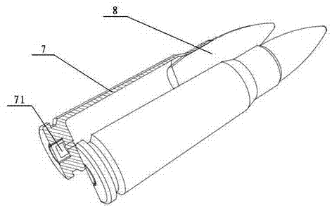
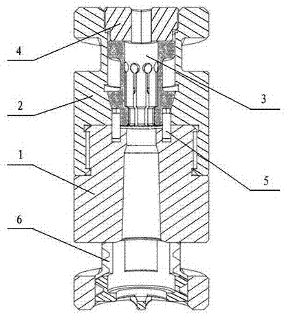
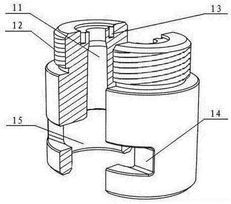
[0028] Such as Figure 2-9 As shown, a bullet dismantling device is composed of a lower base 1, an upper base 2, an elastic hoop 3, a set nut 4, a stop pin 5 and a rubber plug 6, and the upper end of the lower base 1 It is threadedly connected with the lower end of the upper base 2 through the lower disassembly thread 12 of the lower base 1 and the upper disassembly thread 22 of the upper base 2, and the center of the lower base 1 has a shell profiling tapered surface 11 for holding bullet shells , the upper end is processed with the lower pin hole 13 of the anti-rotation pin, and the lower end is processed with a plug matching hole 15 for inserting the rubber plug 6; the center o...


PUM


Abstract

The invention discloses a cartridge dismounting device. The cartridge dismounting device is characterized by consisting of a lower pedestal, an upper pedestal, an elastic hoop, a fastening screw cap, a rolling stopper pin and a rubber choke plug, wherein the upper end of the lower pedestal is connected with the lower end of the upper pedestal through threads; a cartridge case copying tapered surface for accommodating an cartridge case is arranged on the center of the lower pedestal, and a lower pin hole is formed in the upper end of the lower pedestal; a hoop matching tapered surface and a hoop guide surface are arranged on the center of the upper pedestal for fixing the elastic hoop; a cylindrical clamping surface is processed on the center of the elastic hoop for clamping a cartridge bullet, and the outer side surface of the elastic hoop is a locking tapered surface; an upper pin hole is distributed in the outer periphery of the elastic hoop, a reducing ring is arranged on the middle part of the elastic hoop, and a cylindrical guide surface is arranged on the upper part of the elastic hoop; an elastic deformation slot and a crack-preventing hole are distributed in the locking tapered surface and the reducing ring; the elastic hoop is fixedly arranged in the upper pedestal for fixing the fastening screw cap, and is fixed with the lower pedestal through the rolling stopper pin; and the rubber choke plug is fixedly arranged in the lower pedestal. The cartridge dismounting device is delicate, simple and reliable in structure, is convenient to operate, and does not affect the re-mounting and follow-up using effect after the cartridge is dismounted while a dismounting process is guaranteed to be stable and safe.

Description

technical field [0001] The patent of the present invention relates to the fields of firearm use, scientific research, production and the like, and especially belongs to a bullet dismantling device. Background technique [0002] In the process of R&D, production, testing and even use of civilian firearms, scientific research, production units or civilian gun users often have the need to dismantle bullets, such as: measuring the amount of propellant charge, changing the charge amount of propellant or even changing Types of propellant, and then reloading bullets to meet the needs of scientific research, production, testing or special shooting purposes of different users. [0003] When simply using general-purpose tools such as vise and tool pliers to disassemble the bullet by clamping, the entire disassembly process will be difficult to control due to personal operating skills and low proficiency. At this time, the bullet’s sensitive primer and The propellant has not yet exp...

Claims


Application Information

Patent Timeline
IPC IPC(8): F42D5/04
CPCF42D5/04
Inventor 马玉石郑炳生王通钟银珠林建鑫蒋正记黄国林陈敏
Owner FUJIAN ORDNANCE EQUIP
Learn More