
Stamping die with top guide limiting mechanism

A technology of guiding and limiting mechanism and stamping die, applied in the field of stamping die, can solve the problems of simple structure, affecting the service life of stamping die, trouble, etc., and achieve the effect of improving safety and functionality

Inactive Publication Date: 2017-11-07
黄石市鑫楚精密模具股份有限公司
View PDF0 Cites 0 Cited by
  • Summary
  • Abstract
  • Description
  • Claims
  • Application Information

AI Technical Summary

Problems solved by technology

The current stamping die has a simple structure and a single function. During the stamping process, the matching accuracy between the punch and the stamping groove seriously affects the service life of the entire stamping die. Once an error occurs, it is easy to cause the die to be scrapped. The current safety protection device for the stamping die The cost is very high, mainly relying on the operator to debug during the installation process, and also need to try to adjust, which is very troublesome

Method used


Image

  • Stamping die with top guide limiting mechanism
  • Stamping die with top guide limiting mechanism

Examples


Embodiment Construction

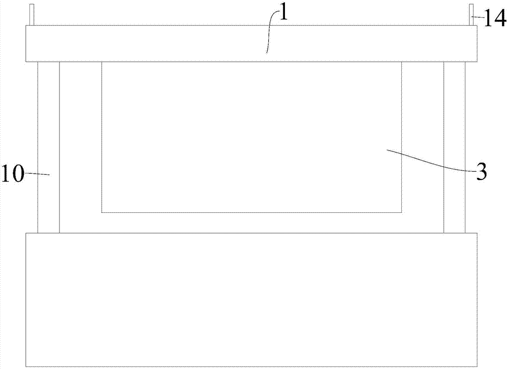
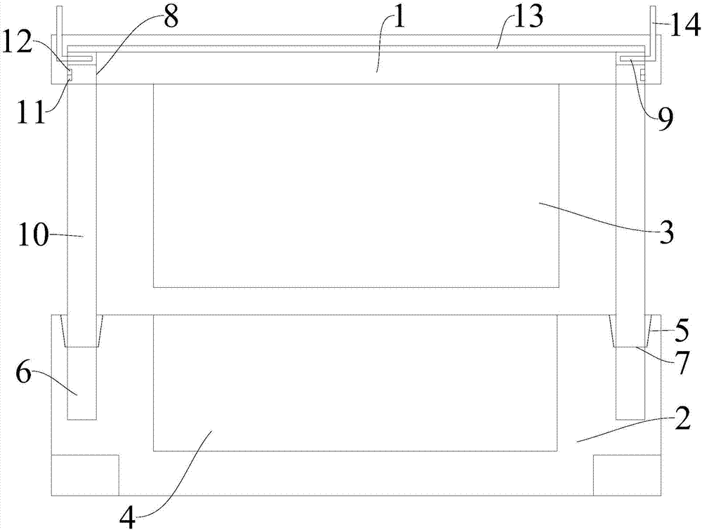
[0013] The present invention is described in further detail now in conjunction with accompanying drawing. These drawings are all simplified schematic diagrams, which only illustrate the basic structure of the present invention in a schematic manner, so they only show the configurations related to the present invention.

[0014] figure 1 and figure 2 The stamping die shown has a top guide and limit mechanism, including an upper template 1 and a lower template 2, the lower end of the upper template 1 has a downwardly protruding punch 3, and the upper surface of the lower template 2 is provided with a punch corresponding to the punch 3. Matched stamping groove 4, the upper surface of the lower template 2 is located around the stamping groove 4 and is provided with an upper guide cone hole 5, and the inner bottom surface of the upper guide cone hole 5 is provided with a lower guide blind hole 6, and the lower end of the upper guide cone hole 5 is opened and the lower guide The ...


PUM


Abstract

The invention relates to the technical field of stamping production equipment, in particular to a stamping die with a top guiding and limiting mechanism, including an upper template and a lower template. The upper surface of the lower template is located around the stamping groove and is provided with an upper guide taper hole, and the inner bottom surface of the upper guide cone hole is provided with a lower guide blind hole. A stamping die with a top guide limit mechanism of the present invention adopts the upper extrusion control hole to set the vertical extrusion rod inside, and the upper guide taper hole and the lower guide hole matched with the vertical extrusion rod are set on the lower template. Blind hole, using the metal extrusion shrapnel inside the upper extrusion control hole and the metal connecting piece to cooperate to automatically control the closing of the power device according to the actual situation, greatly improving the safety and functionality of the entire stamping die.

Description

technical field [0001] The invention relates to the technical field of stamping production equipment, in particular to a stamping die with a top guiding and limiting mechanism. Background technique [0002] Stamping is a pressure processing method that uses a mold installed on a press to apply pressure to the material to cause separation or plastic deformation to obtain the required parts. Stamping die is a special process equipment for processing materials (metal or non-metal) into parts (or semi-finished products) in cold stamping processing, called cold stamping die (commonly known as cold stamping die). The current stamping die has a simple structure and a single function. During the stamping process, the matching accuracy between the punch and the stamping groove seriously affects the service life of the entire stamping die. Once an error occurs, it is easy to cause the die to be scrapped. The current safety protection device for the stamping die The cost is very high,...

Claims


Application Information

Patent Timeline
IPC IPC(8): B21D37/12B21D55/00
CPCB21D37/12B21D55/00
Inventor 柯细兰
Owner 黄石市鑫楚精密模具股份有限公司
Learn More