
Push-pull type electric oven device

An electric oven, push-pull technology, applied in the field of push-pull electric oven devices, can solve the problems of low food efficiency, wear and tear, increase investment cost, etc., and achieve convenient food placement and removal, simple device structure, safe and reliable operation. Effect

Active Publication Date: 2017-11-07
中山市劲鑫电器有限公司
View PDF7 Cites 0 Cited by
  • Summary
  • Abstract
  • Description
  • Claims
  • Application Information

AI Technical Summary

Problems solved by technology

[0002] Electric ovens are used more and more widely in food processing and production, while the previous electric ovens are structurally integrated, with a storage cavity inside to place food, and the food is heated and baked through the heating walls around it; The storage cavity is fixed inside the electric oven, so it is troublesome to place or take out food; in the past, one end of the electric oven door is connected to the storage cavity by a hinge shaft, and the other end is engaged with the storage cavity by a lock. Only a little force is needed to open the electric oven door, so the lock between the electric oven door and the storage cavity is unstable, and it is easy to cause temperature loss in the oven, which makes the food processing unevenly heated, and the heating and baking effect of the food cannot be achieved. All are single-type ovens, which are inefficient for baking food that requires a lot of heating; and the hinge shaft is a wearable object, which is prone to wear and tear after repeated use and needs to be replaced, increasing investment costs

Method used


Image

  • Push-pull type electric oven device
  • Push-pull type electric oven device
  • Push-pull type electric oven device

Examples


Embodiment Construction

[0017] The preferred embodiments of the present invention will be described in detail below in conjunction with the accompanying drawings, so that the advantages and features of the present invention can be more easily understood by those skilled in the art, so as to define the protection scope of the present invention more clearly.

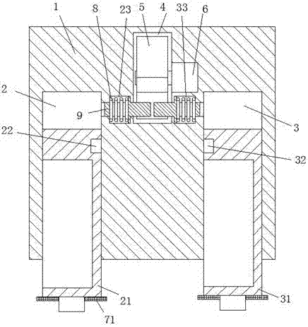
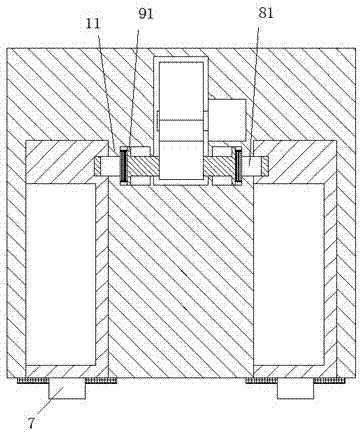
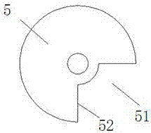
[0018] refer to Figure 1-5 A push-pull electric oven device is shown, including a frame 1, a left retraction cavity 2 and a right retraction cavity 3 arranged in the frame 1, and a left retraction cavity 2 and a right retraction cavity which can slide inside and outside respectively 3, the left cabinet 21 and the right cabinet 31, and the left fixed hole 22 arranged at the rear right side of the left cabinet 21, and the right fixed hole 32 arranged at the left rear side of the right cabinet 31, the frame 1 Located in the middle of the left retraction chamber 2 and the right retraction chamber 3, there is a clamping groove 120, and a clamp 12 is ...


PUM


Abstract

The invention discloses a push-pull type electric oven device comprising a framework (1), a left withdrawing cavity (2) disposed in the framework (1) and a right withdrawing cavity (3) disposed in the framework (1), a left case cabinet (21) disposed in the left withdrawing cavity (2) and capable of sliding inwardly and outwardly and a right case cabinet (31) disposed in the right withdrawing cavity (3) and capable of sliding inwardly and outwardly, a left positioning hole (22) formed behind the right side of the left case cabinet (21) and a right positioning hole (32) formed behind the left side of the right case cabinet (31). A left chute (23) and a right chute (33) are further disposed in the framework (1); a force-applying device accommodating cavity (4) is arranged between the left chute (23) and the right chute (33) and communicates with the two chutes; the left chute (23) communicates with the inner side of the left recovering cavity (2); the right chute (33) communicates with the inner side of the left recovering cavity (3); and spacing assemblies capable of sliding left to right and being symmetric are respectively disposed in the left chute (23) and the right chute (33).

Description

technical field [0001] The invention relates to a push-pull electric oven device. Background technique [0002] Electric ovens are used more and more widely in food processing and production, while the previous electric ovens are structurally integrated, with a storage cavity inside to place food, and the food is heated and baked through the heating walls around it; The storage cavity is fixed inside the electric oven, so it is troublesome to place or take out food; in the past, one end of the electric oven door is connected to the storage cavity by a hinge shaft, and the other end is engaged with the storage cavity by a lock. Only a little force is needed to open the electric oven door, so the lock between the electric oven door and the storage cavity is unstable, and it is easy to cause temperature loss in the oven, which makes the food processing unevenly heated, and the heating and baking effect of the food cannot be achieved. They are all single-type ovens, which are i...

Claims


Application Information

Patent Timeline
Patent Type & Authority Applications(China)
IPC IPC(8): A21B1/00E05B63/14E05B47/00E05B65/00E05B15/00E05B15/10
CPCA21B1/00E05B15/00E05B15/10E05B47/0001E05B63/146E05B65/00
Inventor 施姣女
Owner 中山市劲鑫电器有限公司
Learn More