
a tracker

A technology for projectiles and launchers, which is applied in the field of tracking projectiles, can solve the problems that projectiles cannot track targets and have low strike accuracy, and achieve the effects of improving tracking capabilities, improving production efficiency, and facilitating assembly and production

Active Publication Date: 2019-02-12
山东诚阳电缆有限公司
View PDF7 Cites 0 Cited by
  • Summary
  • Abstract
  • Description
  • Claims
  • Application Information

AI Technical Summary

Problems solved by technology

[0005] Therefore, the technical problem to be solved by the present invention is to overcome the technical defects that the launcher in the prior art cannot track the target and the strike accuracy is low

Method used


Image

  • a tracker
  • a tracker
  • a tracker

Examples


Embodiment 1

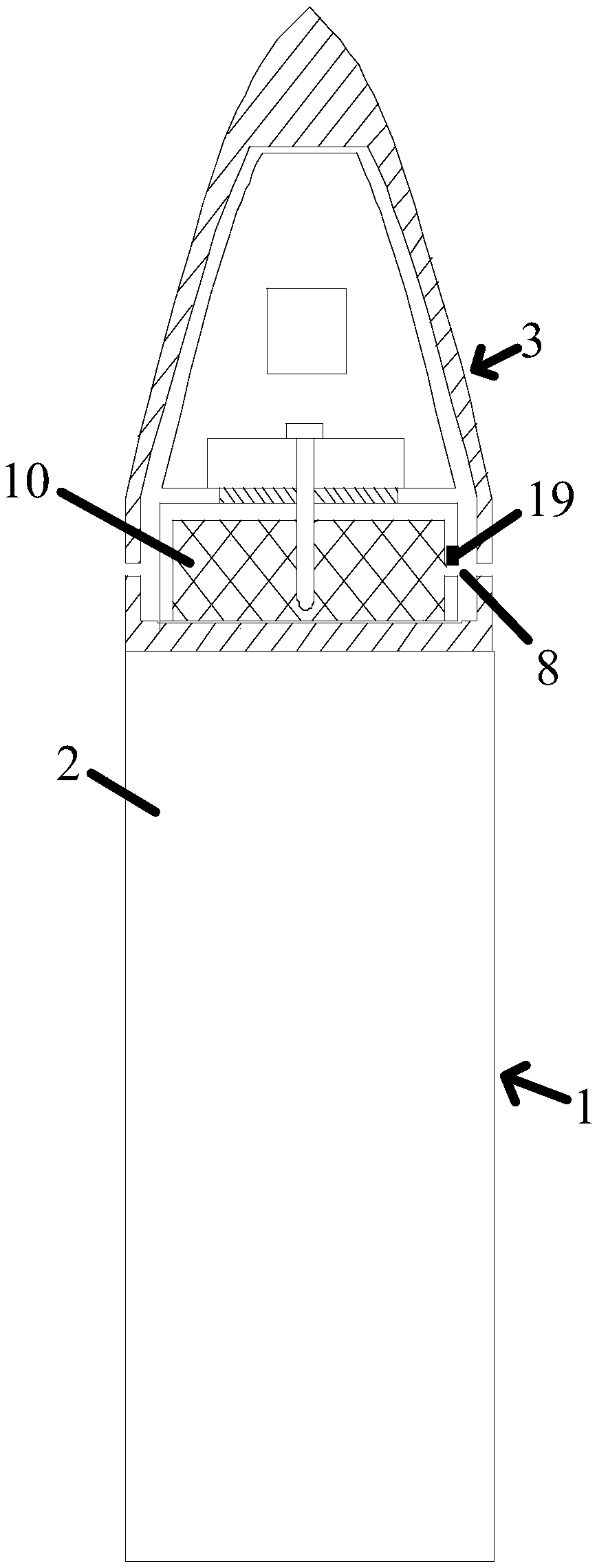
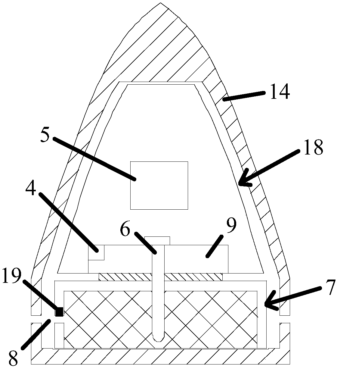
[0044] Such as figure 1 and figure 2 The tracked projectile shown is a bullet, which consists of:

[0045] The signal transmitter is pre-set on the tracked target and is used to transmit position signals;

[0046] The projectile body 1 is provided with a primary motive medium 2 in the inner cavity of the projectile body 1;

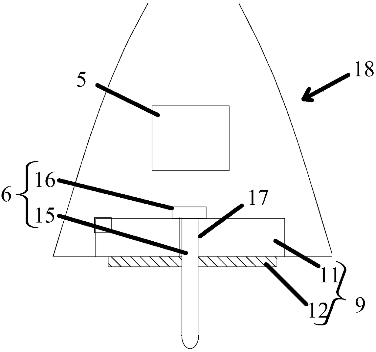
[0047] The launcher 3 is a bullet that does not rotate during flight, and is arranged on the front end of the projectile body 1. It includes a signal receiver 4 and an excitation structure 6 arranged in the inner cavity of the launcher 3, and accommodates a secondary kinetic medium. The disc-shaped power chamber 7 of 10, the secondary power medium 10 is propellant and the power chamber 7 is provided with at least one injection channel 8 extending to the outside of the side of the firing head 3, as Figure 4 As shown, the injection channel 8 is arranged in the circumferential direction of the power chamber 7 and the control valve 19 for controlling the...

Embodiment 2

[0057] Such as figure 1 and figure 2 The tracked projectile shown is a bullet, which consists of:

[0058] The signal transmitter is pre-set on the tracked target and is used to transmit position signals;

[0059] The projectile body 1 is provided with a primary motive medium 2 in the inner cavity of the projectile body 1;

[0060] The launcher 3 is a bullet that does not rotate during flight, and is arranged on the front end of the projectile body 1. It includes a signal receiver 4 and an excitation structure 6 arranged in the inner cavity of the launcher 3, and accommodates a secondary kinetic medium. The disc-shaped power chamber 7 of 10, the secondary power medium 10 is propellant and the power chamber 7 is provided with at least one injection channel 8 extending to the outside of the side of the firing head 3, as Figure 4 As shown, the injection channel 8 is arranged in the circumferential direction of the power chamber 7 and the control valve 19 for controlling the...


PUM


Abstract

The invention provides a tracking emitter. The tracking emitter comprises a signal emitter, an emitter body, an emitting head and a power house controlling mechanism, wherein the emitting head comprises a signal receiver and an exciting structure which are arranged in an inner cavity of the emitting head and a power house containing a secondary power medium; at least one ejecting channel extending to the exterior of the side of the emitting head is arranged in the power house to excite the secondary power medium in the power house; the signal receiver is used for receiving emitting position signals and sending excitation control commands and power control commands; the exciting structure is used for receiving the excitation control commands and exciting the secondary power medium in the power house; and the power house controlling mechanism is in drive connection with the power house and is used for receiving the power control commands and driving the power house to rotate in the circumferential direction of the emitting head so as to change the ejecting direction of the ejecting channel. By means of the tracking emitter, the problems that emitters are incapable of tracking objects and low in strike accuracy in the prior art are solved.

Description

technical field [0001] The invention belongs to the technical field of launching devices, is suitable for non-rotating and advancing projectiles, and in particular relates to a tracking projectile. Background technique [0002] Projectiles in the prior art mainly include a projectile body and a projectile head. When the trigger is pulled, the projectile head is excited to separate from the projectile body and shoot out from the gun bore to hit the target. If the position of the target changes, after the projectile is fired from the barrel, since the launch head can only move in one direction, it is impossible to strike the target precisely, which reduces the accuracy of the strike. [0003] In order to solve the above technical problems, Chinese patent document CN 105498254 A discloses a emitter, such as Figure 7 As shown, it comprises: emitter body body 101; emitter body 102, has the channel 103 of rear end opening; There is an installation cavity, and the launcher cap 10...

Claims


Application Information

Patent Timeline
Patent Type & Authority Patents(China)
IPC IPC(8): F42B12/02F42B10/66
CPCF42B10/668F42B12/02
Inventor 王海龙
Owner 山东诚阳电缆有限公司
Learn More