A solar heat collection system

A technology of solar heat collection and solar heat collector, applied in the field of solar heat collection system, can solve the problems of limited service life, prolonging the time period of energy saving and recovery cost of solar energy equipment, etc.

Pending Publication Date: 2017-11-03
TIANPU NEW ENERGY TECH
View PDF1 Cites 0 Cited by
  • Summary
  • Abstract
  • Description
  • Claims
  • Application Information

AI Technical Summary

Problems solved by technology

[0003] Among them, the circulation between the solar collector and the heat preservation water tank is carried out through the circulation pipe. The circulation pipe needs to have good heat preservation. The circulation pipe includes the upper circulation and the lower circulation. The process of pumping water from the heat collector, and then pushing the hot water into the heat preservation water tank through the upper part of the heat collector is called upper circulation. When the circulation pump rotates in the circulation pipe of the solar heat collection system, water flows in the circulation pipe. In the unpressurized solar collector In the thermal system (solar heat collection system is divided into pressure-bearing system and non-pressure-bearing system, which is defined as below 0.8KG and above 0.8KG), when the circulating water pump stops, there is no water in the upper circulation pipe, and ordinary heat preservation is required. It is necessary to install electric heating cables and other auxiliary heating and heat preservation measures, but there is always water in the lower circulation pipeline. When the water pump stops, a check valve needs to be installed on the pipeline in front of the water pump to prevent the heat collection system from being damaged due to lack of water. After air-drying, the solar heat collector tubes will explode when exposed to water. Once the tubes are exploded, the entire system will not be able to operate. Only by replacing the broken tubes can it operate normally. Therefore, the lower circulation pipeline needs better heat preservation because there is always water. In order to avoid freezing the pipes and freezing the water in the pipes, in addition to the normal heat preservation materials, electric heating cables should be laid inside the upper insulation of the pipes. The electric heating cables rely on electric energy and have a limited service life, so as to extend the energy-saving and recovery cost years of solar energy equipment.

Method used


Image

  • A solar heat collection system
  • A solar heat collection system
  • A solar heat collection system

Examples


Embodiment Construction

[0024] The specific embodiments of the present invention will be described in detail below in conjunction with the accompanying drawings.

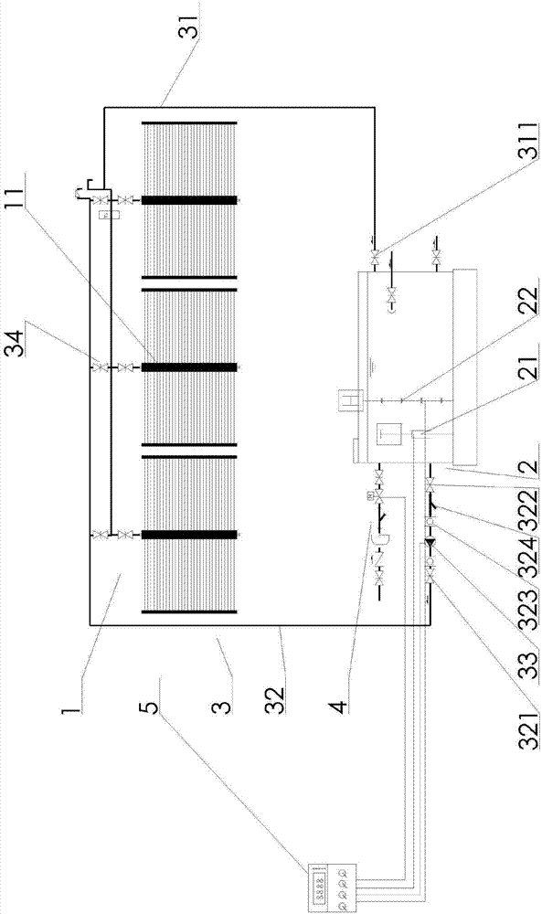
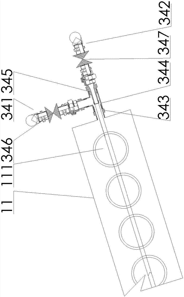
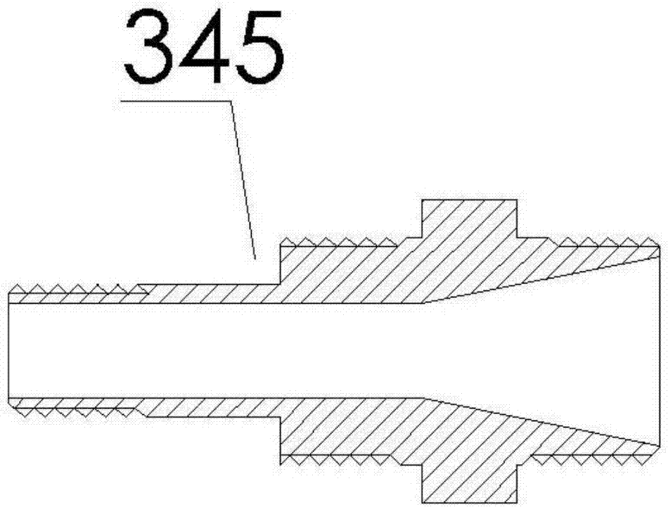
[0025] as attached Figure 1-3 Shown, a kind of solar heat collecting system comprises solar heat collector 1, thermal insulation water tank 2 and water circulation system 3, and described solar heat collector 1 and described thermal insulation water tank 2 communicate through described water circulation system 3, and described water circulation system 3 includes a first circulation pipe 31, a second circulation pipe 32, a circulation pump 33 and a three-way connector 34, and one end of the first circulation pipe 31 and one end of the second circulation pipe 32 pass through the three-way connector 34 is communicated with the solar heat collector 1, the other end of the first circulation pipe 31 and the other end of the second circulation pipe 32 are communicated with the heat preservation water tank 2, and the circulation pump 33 is commun...


PUM


Abstract

The invention provides a solar heat collection system comprising a solar heat collector, a heat preservation water tank and a water circulation system. The solar heat collector and the heat preservation water tank communicate with each other via the water circulation system. The water circulation system comprises a first circulation pipe, a second circulation pipe, a circulation pump and a tee joint; one end of the first circulation pipe and one end of the second circulation pipe communicate with the solar heat collector via the tee joint; the other end of the first circulation pipe and the other end of the second circulation pipe communicate with the heat preservation water tank; the circulation pump communicates with the second circulation pipe; the tee joint comprises a first circulation pipe connecting pipe, a second circulation pipe connecting pipe, a heat collector connection collecting tank connector and a t-branch pipe. The solar heat collection system can prevent freezing damage or inside freezing of the second circulation pipe without an electric heat tracing belt.

Description

technical field [0001] The invention belongs to the technical field of solar heat collecting devices, and in particular relates to a solar heat collecting system. Background technique [0002] The vacuum tube solar hot water system uses a circulating water pump to transfer heat between the solar collector and the heat preservation water tank, circulates the high temperature hot water from the collector to the heat preservation water tank, and then circulates the low temperature water from the heat preservation water tank to the solar heat collector. The solar heat collection system is such a cycle. The cycle mainly relies on the intelligent controller to detect the temperature difference between the solar collector and the thermal insulation water tank to control the water pump cycle. When the water temperature of the thermal insulation water tank and the solar thermal collector reaches a balance, the circulating water pump stops. Running, to the set temperature difference c...

Claims


Application Information

Patent Timeline
IPC IPC(8): F24J2/05F24J2/24F24J2/46F24J2/40F24S10/40F24S10/70
CPCF24S10/40F24S40/60F24S50/00Y02E10/44
Inventor 牛传武程翠英
Owner TIANPU NEW ENERGY TECH
Why Eureka
Try Eureka