Torque end point detection method and detection device

A detection method and detection device technology, applied in the direction of grinding devices, semiconductor/solid-state device testing/measurement, grinding machine tools, etc., can solve the problem of reducing material removal rate and optimizing material selection ratio, narrow process window, product differences, etc. problem, to achieve the effect of improving the accuracy of end point detection and widening the process window

Active Publication Date: 2019-03-12
HWATSING TECH +1
View PDF7 Cites 0 Cited by
  • Summary
  • Abstract
  • Description
  • Claims
  • Application Information

AI Technical Summary

Problems solved by technology

However, in the actual industrial production process, the capture of the termination point generally has an error of 5s or even longer, resulting in differences between products of the same batch. In the process of 55nm and above, the above errors brought about The difference in material thickness has little effect on the quality of the wafer, but in the process below 28 / 40nm, the above error will seriously affect the yield of the wafer
[0003] In the related technology, the method of replacing the corresponding consumables is adopted to reduce the material removal rate and optimize the material selection ratio. However, due to inherent principle defects, it is difficult to accurately grasp the polishing termination point, resulting in under- or over-throwing of the medium, resulting in inability to Extend the corresponding technology of 55nm process to 28 / 40nm process, and the process window is narrow, which needs to be solved urgently

Method used


Image

  • Torque end point detection method and detection device
  • Torque end point detection method and detection device
  • Torque end point detection method and detection device

Examples


Embodiment Construction

[0026] Embodiments of the present invention are described in detail below, examples of which are shown in the drawings, wherein the same or similar reference numerals designate the same or similar elements or elements having the same or similar functions throughout. The embodiments described below by referring to the figures are exemplary and are intended to explain the present invention and should not be construed as limiting the present invention.

[0027] The following describes the detection method and detection device of the torque end point according to the embodiments of the present invention with reference to the accompanying drawings. Firstly, the detection method of the torque end point according to the embodiments of the present invention will be described with reference to the accompanying drawings.

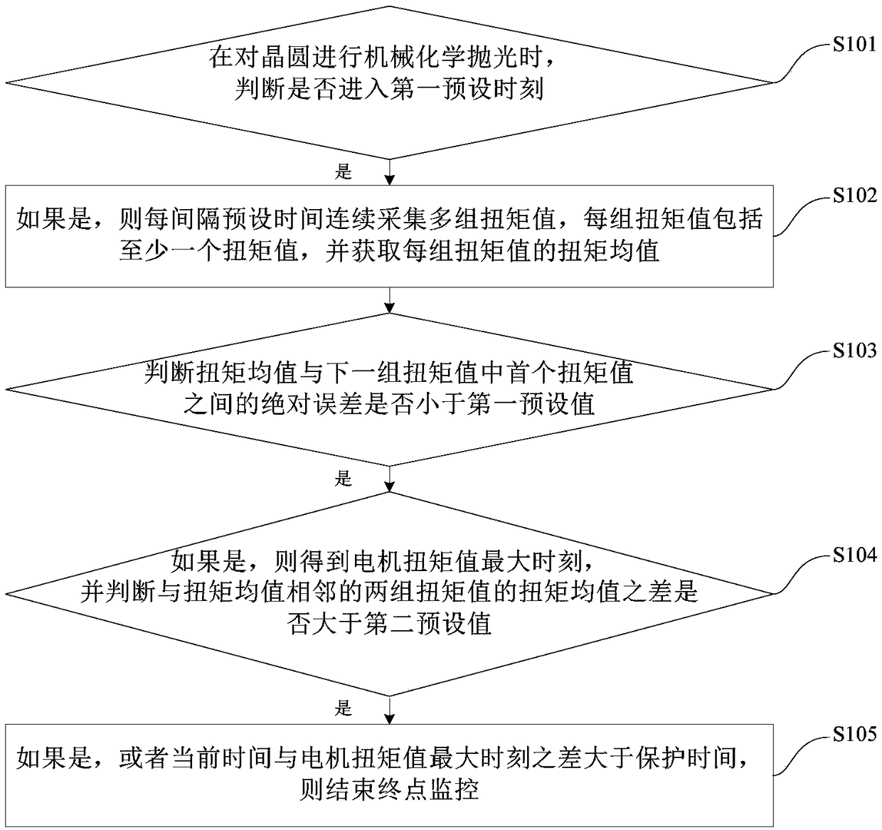
[0028] figure 1 It is a flow chart of the detection method of the torque end point according to an embodiment of the present invention.

[0029] Such as figure 1 As...


PUM


Abstract

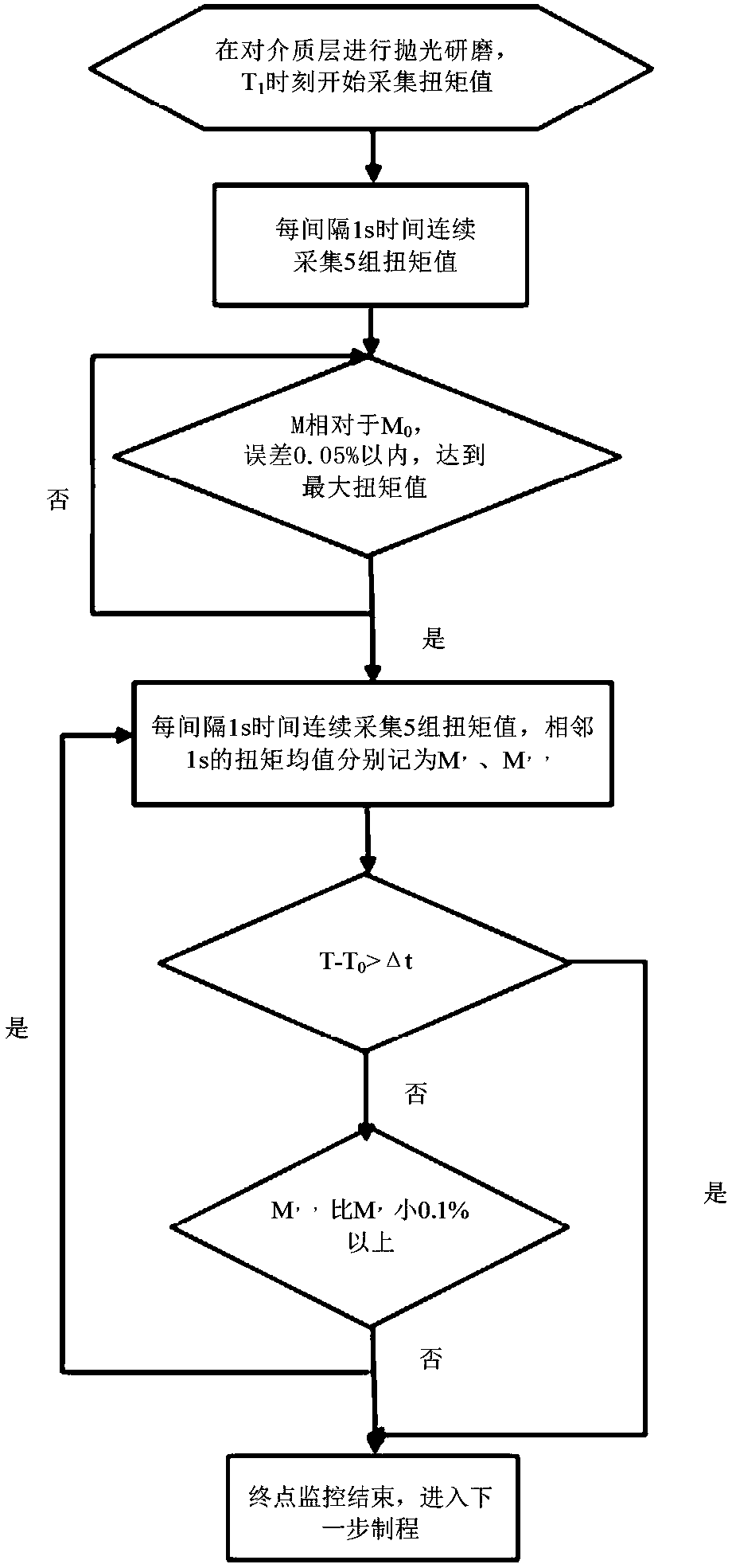
The invention discloses a torque end point detection method and detection device. The torque end point detection method comprises the following steps: when subjecting a wafer to chemical mechanical polishing, judging whether the first preset time is reached or not; if yes, continuously acquiring a plurality of groups of torque valves at intervals of the first preset time, and acquiring the torque mean of each group of torque values, wherein each group of torque values comprise at least one torque value; judging whether the absolute error between the torque mean and the first torque value in the next group of torque values is less than the first preset value or not; if yes, acquiring the time when the maximum motor torque value is reached, and judging whether the difference between the torque means of the two groups of torque values adjacent to the above torque mean is greater than the second preset value or not; and if yes or if the difference between the current time between the time when the maximum motor torque value is reached is greater than the protection time, finishing the end point monitoring. By adoption of the torque end point detection method, the inherent defect in a conventional torque end point detection method can be further overcome, the end point detection precision can be improved, and the corresponding process window can be widened.

Description

technical field [0001] The invention relates to the technical field of chemical mechanical polishing, in particular to a detection method and a detection device of a torque end point. Background technique [0002] At present, the detection method of the torque end point is generally to monitor the starting point and the ending point in the polishing process. However, in the actual industrial production process, the capture of the termination point generally has an error of 5s or even longer, resulting in differences between products of the same batch. In the process of 55nm and above, the above errors brought about The difference in material thickness has little effect on the quality of the wafer, but in the process below 28 / 40nm, the above errors will seriously affect the yield of the wafer. [0003] In the related technology, the method of replacing the corresponding consumables is adopted to reduce the material removal rate and optimize the material selection ratio. Howe...

Claims


Application Information

Patent Timeline
Patent Type & Authority Patents(China)
IPC IPC(8): B24B37/013H01L21/306H01L21/66
CPCB24B37/013H01L21/30625H01L22/12
Inventor 张敬业路新春沈攀
Owner HWATSING TECH
Why Eureka
Try Eureka