
Impact testing device for debris flow protection structure

A protective structure and impact test technology, which is applied in the testing of machines/structural components, measuring devices, impact tests, etc., can solve the problem that the test device that does not simulate the impact of debris flow, the impact force and the impact process cannot accurately simulate the protective structure Problems such as continuous impact effect, to achieve the effect of improving test efficiency

Active Publication Date: 2017-10-27
INST OF MOUNTAIN HAZARDS & ENVIRONMENT CHINESE ACADEMY OF SCI
View PDF16 Cites 3 Cited by
  • Summary
  • Abstract
  • Description
  • Claims
  • Application Information

AI Technical Summary

Problems solved by technology

The chute test can simulate the impact of debris flow on the protective structure to a certain extent, but it is limited by its size, and its impact force and impact process cannot accurately simulate the continuous impact of high-speed debris flow on the protective structure
In addition, different mountain terrains require different protective structures. At present, steel-concrete structure-based plate protective structures and steel wire mesh-based mesh protective structures are used more, especially for the protection of new structures or new materials. The structure needs to be tested to verify the design, and the current equipment cannot simulate the protection capabilities of the above two continuous impacts on the same equipment
To sum up, although there are many impact test devices at present, there is no test device that can be directly applied to simulate the impact of debris flow.

Method used


Image

  • Impact testing device for debris flow protection structure
  • Impact testing device for debris flow protection structure
  • Impact testing device for debris flow protection structure

Examples


Embodiment Construction

[0019] The specific embodiment of the present invention will be described with reference to the accompanying drawings.

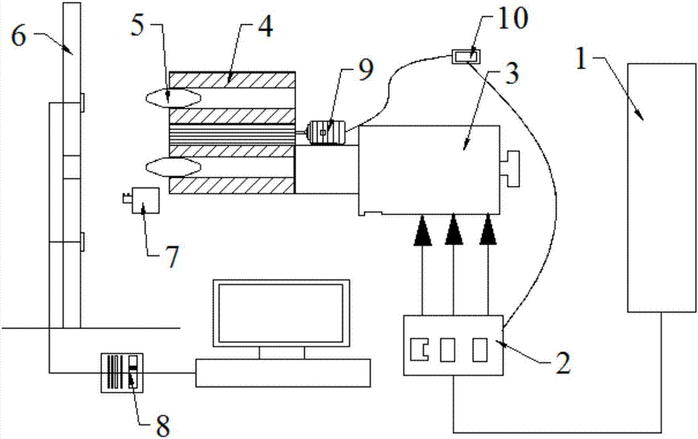
[0020] Such as figure 1 The debris flow protective structure impact test device shown includes a cylinder 1, a launching device 3, a runner 4, a conical impact bullet 5, a high-speed camera 7 and an experimental protective structure 6;

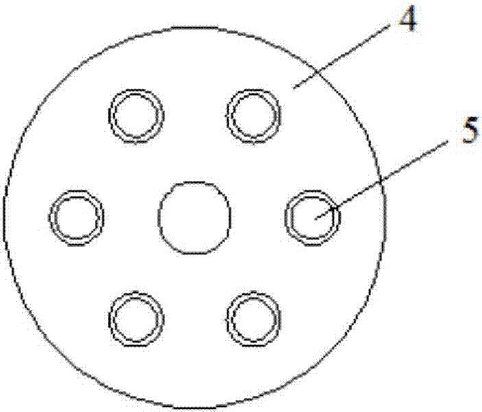
[0021] Cylinder 1 is connected with launcher 3, and launcher 3 is provided with control switch 2 to control the size of impact force; Launcher is connected with cylindrical runner 4, such as figure 2 As shown, the runner 4 has six chambers, and the chambers are respectively equipped with conical impact bullets 5;

[0022] The speed regulating motor 9 is connected with the rotating shaft of the runner 4, and the speed regulating motor 9 and the control switch 2 are respectively connected with the launch speed controller 10;

[0023] An experimental protective structure 6 is installed in front of the launch of the runner 4,...


PUM


Abstract

The invention relates to the technical field of safety protection, specifically an impact testing device for a debris flow protection structure. An air cylinder is connected with a launching device, and the launching device is provided with a control switch so as to control the size of an impact force. The launching device is connected with a cylindrical rotating wheel, and the rotating wheel is provided with six cartridge chambers which respectively store a conical impact bullet. A speed regulating motor is connected with a rotating shaft of the rotating wheel, and the speed regulating motor and the control switch are respectively connected with a launching speed controller. A launching front side of the rotating wheel is provided with an experiment protection structure, and the front of the experiment protection structure is provided with a high-speed camera. The device provided by the invention employs the launching device of the rotating wheel type to achieve the continuous launching of bullets, and can simulate the continuous impact process of a debris flow. The experiment protection structure can be controlled and adjusted, so the device can simulate the debris flow protection structures in different forms. The testing device improves the testing efficiency.

Description

technical field [0001] The invention relates to the technical field of safety protection, in particular to an impact test device for debris flow protection structures. Background technique [0002] In Southwest my country, Tibet, areas with complex landform conditions such as high mountains and deep valleys, and developed cities such as Hong Kong with many mountain disasters, the maximum speed of debris flow hitting the protective structure after acceleration can reach 50-100m / s, and the impact energy is huge. If the interception is carried out in the short-range acceleration stage, the impact of the debris flow on the protective structure is a continuous dynamic impact process. Therefore, the development of the debris flow impact test device needs to solve two problems: [0003] The impact process is a dynamic impact process, so a large impact energy must be provided to the protective structure; [0004] The impact process is a continuous impact process, so it is necessar...

Claims


Application Information

Patent Timeline
Patent Type & Authority Applications(China)
IPC IPC(8): G01M7/08
CPCG01M7/08
Inventor 苏立君肖思友姜元俊李丞
Owner INST OF MOUNTAIN HAZARDS & ENVIRONMENT CHINESE ACADEMY OF SCI
Learn More