Laser calibration device for loading compass

A calibration device and laser technology, applied in the directions of compass, measuring device, surveying and navigation, etc., can solve the problems of complicated adjustment method, difficult to achieve clamping of compass, low accuracy, etc., so as to improve the accuracy of calibration and improve the accuracy of surveying. , the effect of reducing deviation

Pending Publication Date: 2017-10-27
深圳市富盟丰电子有限公司
View PDF0 Cites 0 Cited by
  • Summary
  • Abstract
  • Description
  • Claims
  • Application Information

AI Technical Summary

Problems solved by technology

[0003] 1. After the compass is placed on the support frame, it needs to rely on visual inspection and reference objects to adjust it to the calibration position, such as the longitude and latitude. Only after the reference to the azimuth calibration can accurate survey be realized, but this visual inspection method has visual deviations Large size, multi-person coordination operation, low efficiency, poor survey accuracy and other defects;
[0004] 2. In order to fix the compass at the preset position, the existing support frame is usually equipped with structures such as compass fixtures, positioning holes, and installation holes, but these structures can only be installed with a single type of compass. For a wide variety of compasses on the market It is difficult to achieve clamping, resulting in insufficient compatibility;
[0005] 3. When the compass is placed on the support frame, it is necessary to adjust the compass to a horizontal state. The existing method is to use the level as a reference and adjust the stretching length of the tripod at the same time. However, this method is not only inefficient, but also difficult to level accurately ;
[0006] 4. When it is necessary to calibrate the compass and compass to rotate the compass, it is usually driven by the handle or hand push. The stroke of this adjustment method depends entirely on the user's thrust. The adjustment method is single, and it is difficult to adjust the compass to the specified direction;
[0007] 5. When the compass calibrates the horizontal and vertical lines and the compass does not move, when it is necessary to add marking lines in any angle direction, two people need to hold one end of the line and stand opposite the center of the compass, and one person in the middle looks at the line and guides the compass to take it. Two people on the line rotate the directional marking around the center. This adjustment method is complicated and requires the coordination of multiple people, and the accuracy is low.
[0008] Due to the above deficiencies, the existing compass auxiliary equipment cannot fully play its role, which brings inconvenience to the user's use process

Method used


Image

  • Laser calibration device for loading compass
  • Laser calibration device for loading compass
  • Laser calibration device for loading compass

Examples


Embodiment Construction

[0029] The present invention will be described in more detail below in conjunction with the accompanying drawings and embodiments.

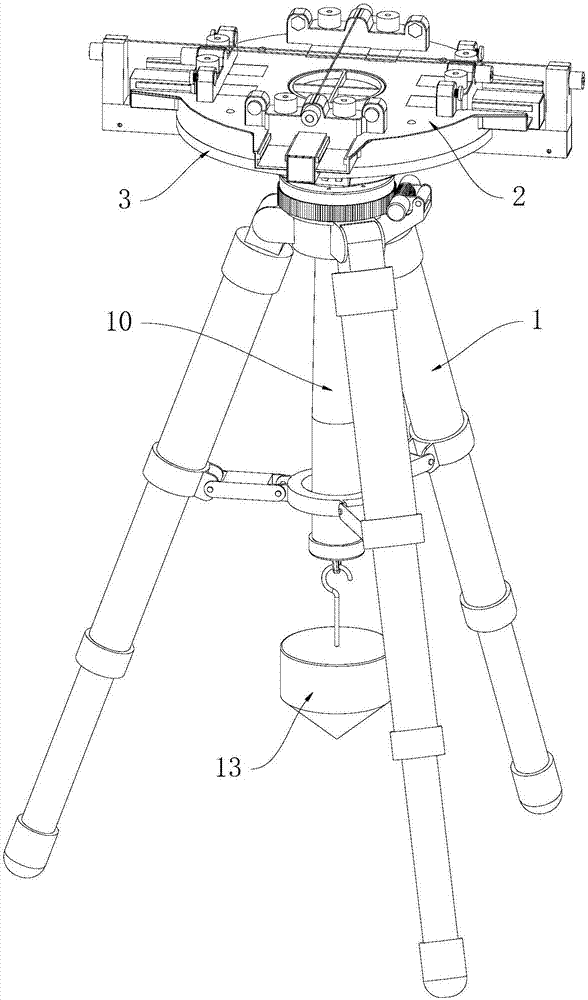
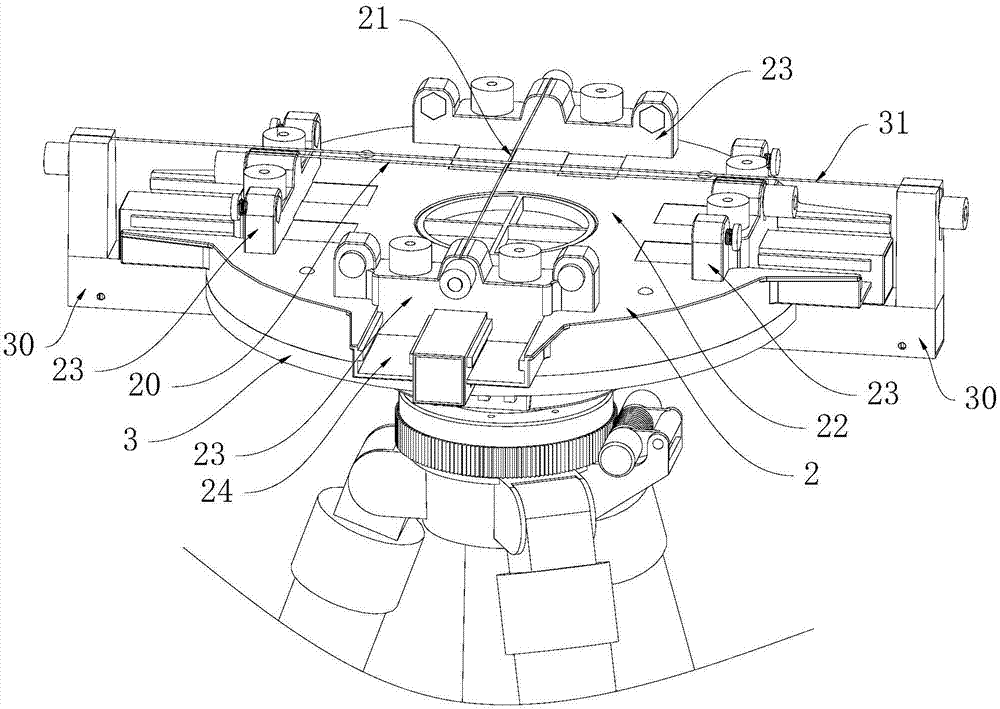
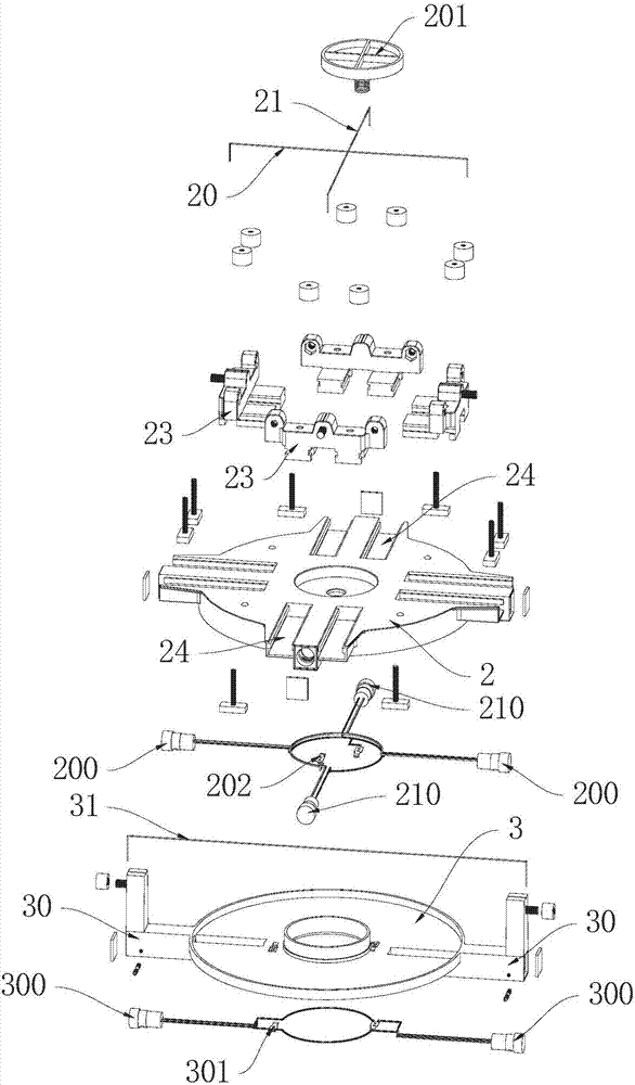
[0030] The invention discloses a laser marking device for loading a compass, which combines Figure 1 to Figure 7 As shown, it includes a support frame 1, and the support frame 1 is provided with a rotatable disk base 2, and the top of the disk base 2 is fixed with a vertically intersecting horizontal marking line 20 and a longitudinal marking line 21. The intersection point of the marking line 20 and the longitudinal marking line 21 is aligned with the axis of the disc base 2, and the top of the disc base 2 is formed with a mounting position 22 for placing a compass, and the mounting position 22 is located between the horizontal marking line 20 and the longitudinal marking line. Below the marking line 21, two horizontal laser emitters 200 and two longitudinal laser emitters 210 are installed on the side of the disc base 2, and the laser beams em...


PUM


Abstract

The invention discloses a laser marking device for loading a compass, which includes a support frame, on which a rotatable disk seat is arranged, and vertically intersecting horizontal marking lines and longitudinal marking lines are fixed on the top of the disk seat. Marking line, the intersection of the horizontal marking line and the longitudinal marking line is aligned with the axis of the disc base, and the top of the disc base is formed with an installation position for placing a compass, and the installation position is located between the horizontal marking line and the longitudinal marking line. Below the line, two horizontal laser emitters and two vertical laser emitters are installed on the side of the disk base, and the laser beams emitted by the two horizontal laser emitters are respectively flush with the extension lines at both ends of the horizontal marking line. The laser beams emitted by the two longitudinal laser emitters are respectively flush with the extension lines at both ends of the longitudinal marking line. The invention can quickly adjust to the calibration direction without relying on visual inspection, and can use laser beams to indicate the direction at the same time, which not only reduces the deviation caused by visual inspection, but also greatly improves the survey accuracy.

Description

technical field [0001] The invention relates to compass bearing and operating equipment, in particular to a laser marking device for loading a compass. Background technique [0002] The compass is an instrument used for geographic survey. During its application, it needs to be placed on a stable support frame to observe data accurately. For this, support equipment similar to camera tripods appeared on the market to serve as auxiliary support. effect, but these existing supporting equipment only have the effect of placing and supporting, and in its actual application process, there are still following defects: [0003] 1. After the compass is placed on the support frame, it needs to rely on visual inspection and reference objects to adjust it to the calibration position, such as the longitude and latitude. Only after the reference to the azimuth calibration can accurate survey be realized, but this visual inspection method has visual deviations Large size, multi-person coord...

Claims


Application Information

Patent Timeline
Patent Type & Authority Applications(China)
IPC IPC(8): G01C17/38
CPCG01C17/38
Inventor 陈汉年
Owner 深圳市富盟丰电子有限公司
Why Eureka
Try Eureka