Angle sliding rail connecting rod device

A connecting rod device and slide rail technology, which is applied to bearings, linear motion bearings, bearing components, etc., can solve the problems of small viewing angle between the platform and the human body, inconvenient use, and difficult to operate, and achieves simple platform fixing and unlocking. Fast, small footprint, convenient height adjustment

Active Publication Date: 2017-10-24
BEIFANG LIANCHUANG COMM
View PDF19 Cites 0 Cited by
  • Summary
  • Abstract
  • Description
  • Claims
  • Application Information

AI Technical Summary

Problems solved by technology

The existing slide rail method mostly adopts reciprocating linear motion, which can only pull the platform horizontally. When adjusting the platform angle, the rear X cross-type connecting rod and chute are mostly used, which is not easy to unlock and occupies space in the height and depth directions.
However, when the platform is pulled out horizontally, since the inclination angle of the platform cannot be changed, the viewing angle between the platform and the human body is small, and there will be a problem that it is not easy to operate, and it is very inconvenient to use.

Method used


Image

  • Angle sliding rail connecting rod device
  • Angle sliding rail connecting rod device
  • Angle sliding rail connecting rod device

Examples


Embodiment Construction

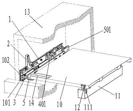
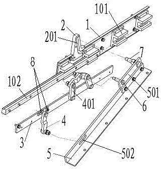
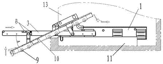
[0011] The present invention will be further described below in conjunction with drawings and embodiments. see Figure 1 to Figure 4 , the angle slide rail connecting rod device, comprising platform 10, slide rail 1, connecting rod 3 and connecting plate 5, slide rail 1 is symmetrically installed on the frame 13 wall panels on both sides of the platform 10; one end of the slide rail 1 A guide seat 2 is installed, and a guide groove 201 is provided on the inner side of the guide seat 2, and a draw-in groove 101 is installed on the inside of the slide rail 1, and a slide bar 102 is inserted in the draw-in slot 101, and the slide bar 102 is connected with the connecting rod 3; A connecting piece 4 is installed on the outer end of the connecting rod 3, and a linking assembly 401 is installed on the inner end, and a limit block 8 is arranged on the top and inside of the connecting piece 4, and the connecting piece 401 is formed by linking four connecting pieces 4. , the connecting...


PUM


Abstract

The invention discloses an angle sliding rail connecting rod device. Sliding rails are symmetrically installed on a frame wallboard and located at the two sides of a platform. Guide bases are arranged at one ends of the sliding rails, and the inner sides of the guide bases are provided with guide grooves. Clamping grooves are installed in the inner sides of the sliding rails, and sliding bars are inserted into the corresponding clamping grooves. The sliding bars are connected with connecting rods. The outer ends of the connecting rods are provided with connecting pieces, and the inner ends of the connecting rods are provided with linkage assemblies. The upper sides and the inner sides of the connecting pieces are both provided with limiting blocks. The connecting pieces at the two ends of the linkage assemblies are connected with the corresponding connecting rods. Connecting shafts are connected with the corresponding connecting pieces, and guide shafts are connected with guide grooves. One side of each connecting plate is connected with the platform. Sliding wheels are arranged under the platform. A pull ring is arranged at the upper side of the platform, and a lock tongue is installed on the outer side edge of the platform. The angle sliding rail connecting rod device has operational ease, the platform can be fixed and unlocked easily and rapidly, the structural stability is high, space occupation is small, and height adjustment is convenient; and meanwhile by changing the dimensions of the connecting rods and the guide bases, the tilting angle of the platform can be changed, and the requirements for the angle sliding rail connecting rod device by platforms of different models are met.

Description

technical field [0001] The invention relates to a slide rail structure device used for a frame or a cabinet platform to realize angular linear motion, in particular to an angle slide rail connecting rod device. Background technique [0002] On the platform of frame or cabinet structure, linear slide rail operation is often required for installation work. The existing slide rail method mostly adopts reciprocating linear motion, which can only pull the platform horizontally. When adjusting the platform angle, the rear X cross-shaped connecting rod and slide groove are mostly used, which is not easy to unlock and occupies space in the height and depth directions. And when the platform is pulled out horizontally, because the inclination angle of the platform cannot be changed, the visual angle between the platform and the human body is small, and the problem of difficult operation will occur, which is very inconvenient to use. Contents of the invention [0003] The technical ...

Claims


Application Information

Patent Timeline
Patent Type & Authority Applications(China)
IPC IPC(8): F16C29/00F16C29/04F16C29/10F16C35/00
CPCF16C29/004F16C29/04F16C29/10F16C35/00Y02E10/50
Inventor 刘亦武钟灶火易珊合
Owner BEIFANG LIANCHUANG COMM
Why Eureka
Try Eureka